คุณยังไม่มีสินค้าในรถเข็น

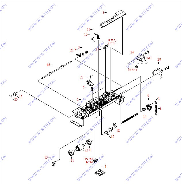
250 Sheet Tray - Center Frame Assembly
| Pic No. | Parts ID | Parts Name | Link |
| 1 | RB1-2190-000CN | Pickup roller spring hook | Find 1 |
| 2 | RB3-0105-000CN | Center support frame (black plastic) - Support structure for the paper pickup roller, feed roller, and paper sensors | Find 2 |
| 2 | RB3-0105-020CN | Center support frame (black plastic) - Support structure for the paper pickup roller, feed roller, and paper sensors | Find 2 |
| 3 | RB3-0165-000CN | Top inner cover (black plastic) - Covers the back half of the pressure roller arms and springs | Find 3 |
| 4 | RB3-0166-000CN | Bottom inner cover (Black) plastic - One covers the paper feed sensor in the center and the other covers sensor wires toward the right side | Find 4 |
| 5 | RS7-0431-000CN | 15 tooth Gear (white plastic) | Find 5 |
| 6 | RS7-0430-000CN | 26 tooth gear - White gear with 1/8th portion of gear cut away and pin for spring tensioning | Find 6 |
| 7 | RS6-2760-000CN | Compression spring | Find 7 |
| 8 | RS6-2025-000CN | Tensioning spring | Find 8 |
| 9 | RS5-1636-000CN | Shaft bushing | Find 9 |
| 10 | RB2-2843-000CN | Torsion spring - Provides a small amount of back pressure for the paper sensor flag | Find 10 |
| 11 | RB2-2892-000CN | Guide roller (Free spinning white plastic roller) - Mounts on the paper pickup drive shaft on each side of the pickup |D| shaped roller | Find 11 |
| 12 | RB2-2895-000CN | Shaft bushing/retainer - Right side pickup roller support bushing | Find 12 |
| 13 | RB2-2896-000CN | Shaft bushing/retainer - Left side pickup roller support bushing | Find 13 |
| 14 | RB2-2897-020CN | Shaft bushing/retainer | Find 14 |
| 14 | RB2-2897-000CN | Shaft bushing/retainer | Find 14 |
| 15 | RS5-1638-000CN | Bushing | Find 15 |
| 16 | RB3-0129-000CN | Feed roller assembly - Includes the metal shaft and two small rubber rollers | Find 16 |
| 16 | RB3-0129-020CN | Feed roller assembly - Includes the metal shaft and two small rubber rollers - Feeds paper from the paper cassette (or tray three below) into the printer - Mounts on the top of the center frame in the base on the 250-sheet input tray assembly | Find 16 |
| 17 | WG8-5593-000CN | Sensor PC board - Small board with flag activated photosensor | Find 17 |
| 17 | WG8-5382-000CN | Sensor PC board - Small board with flag activated photosensor | Find 17 |
| 18 | RB3-0130-000CN | Shaft mounted sensor flag (black plastic) | Find 18 |
| 19 | RB3-0132-000CN | Mechanical sensor flag (black plastic) | Find 19 |
| 20 | RB3-0136-020CN | Solenoid cover/magnetic shield | Find 20 |
| 20 | RB3-0136-000CN | Solenoid cover/magnetic shield | Find 20 |
| 21 | RB3-0137-000CN | Grounding plate | Find 21 |
| 22 | RB3-0161-000CN | Paper pickup roller assembly - Includes the |D| shaped rubber roller on a plastic shaft | Find 22 |
| 23 | RF5-4035-000CN | Pressure roller and arm assembly - Includes the small white roller, the holding arm, and roller scraper | Find 23 |
| 24 | RH7-5347-000CN | Solenoid assembly - Tray 3 (SL95) | Find 24 |
| 24 | RH7-5341-000CN | Solenoid assembly | Find 24 |
| 24 | RH7-5385-000CN | Solenoid assembly - Tray 3 (SL95) | Find 24 |
| 25 | XD9-0136-000CN | Retaining E-ring | Find 25 |
| 25 | XD9-0233-000CN | Retaining E-ring | Find 25 |
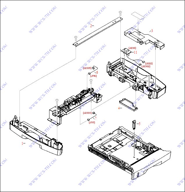
250 Sheet Tray - External Covers
| Pic No. | Parts ID | Parts Name | Link |
| 1 | RB3-0106-000CN | Left side frame/cover (Quartz Gray) plastic - Left side cover and input paper tray guide | Find 1 |
| 2 | RB3-0108-000CN | Metal support cross-brace - Mounts on the top rear of the left and right support frame/cover assemblies | Find 2 |
| 2 | RB3-0108-020CN | Metal support cross-brace - Mounts on the top rear of the left and right support frame/cover assemblies - For the base on the 250-sheet input tray assembly | Find 2 |
| 3 | RB3-0282-000CN | Inner cover - Covers the small interconnecting PC board | Find 3 |
| 4 | RB3-0283-000CN | Inner cover - Covers the bottom of the connector that interconnects the input tray base to the printer | Find 4 |
| 5 | RB2-3019-000CN | Shipping stopper (bright orange plastic) - Helps to prevent damage to the paper tray by restricting the movement of the lift plate (Removed for normal use) | Find 5 |
| 6 | RG5-7139-000CN | Cable assembly | Find 6 |
| 7 | RG5-7138-000CN | Cable assembly | Find 7 |
| 11 | RG5-7149-000CN | Connector assembly - Includes the 14-pin (F) interface connector and cable assembly | Find 11 |
250 Sheet Tray - Paper Cassette Tray

| Pic No. | Parts ID | Parts Name | Link |
| 1 | RG5-6914-040CN | 250 sheet paper tray assembly - Pull out cassette that the paper is loaded into - Does NOT include the paper feed base assembly | Find 1 |
| 1 | RG5-6915-030CN | 250 sheet cassette tray main body assembly - Includes the main structure frame, paper stops, lift plate, springs, and the separation pad assembly - Does NOT include the blue plastic front cover | Find 1 |
| 2 | RB3-0109-000CN | Front cover for the 250 sheet paper cassette tray (Blue) plastic - Has molded in paper loading instructions and a |2| on the front | Find 2 |
| 3 | RF5-4258-020CN | Separation pad assembly - Includes the gray plastic frame with the rubber insert strip - For the cassette on the 250-sheet and 500-sheet input tray assemblies - Mounts in the paper cassette tray assembly | Find 3 |
| 3 | RF5-4258-000CN | Separation pad assembly - Includes the gray plastic frame with the rubber insert strip | Find 3 |
| 4 | RB2-9963-000CN | Separation pad support - Pivoting |L| shaped metal support frame (Does NOT include the separation pad assembly) | Find 4 |
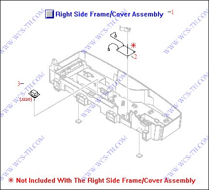
250 Sheet Tray - Right Cover Assembly
| Pic No. | Parts ID | Parts Name | Link |
| 1 | RG5-6919-000CN | Right side frame/cover assembly (Quartz Gray) plastic - Includes the right side cover and paper tray guide, the cassette retainer spring, tray 3 connector, printer interface connector, and rubber feet | Find 1 |
| 2 | RG5-6968-000CN | Interconnecting feed drive PC board | Find 2 |
| 3 | WS1-6336-000CN | Connector assembly - For optional paper tray | Find 3 |
| 3 | RH2-5519-000CN | Connector assembly - For optional paper tray | Find 3 |
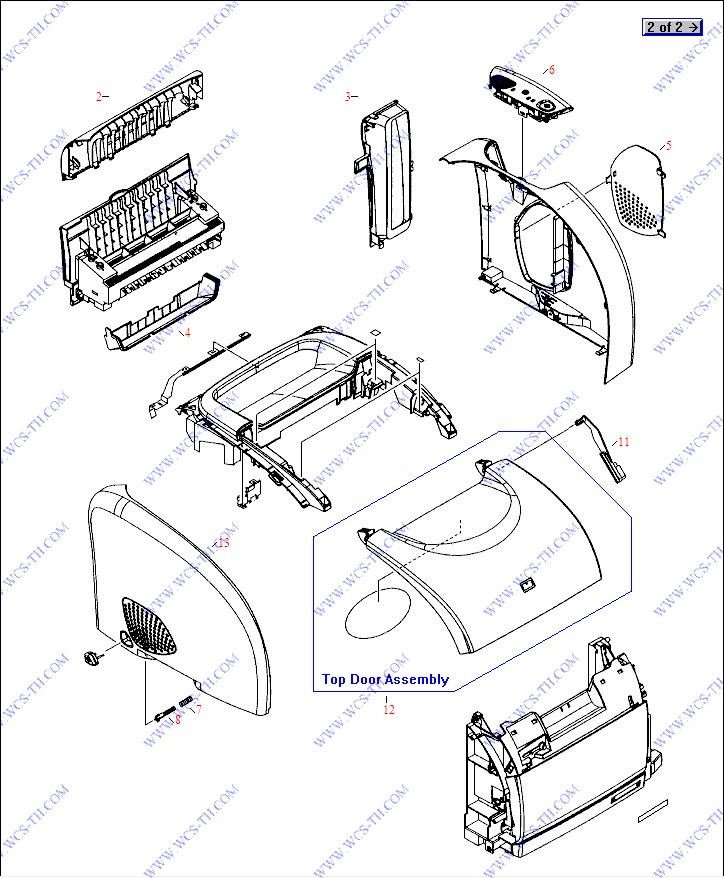
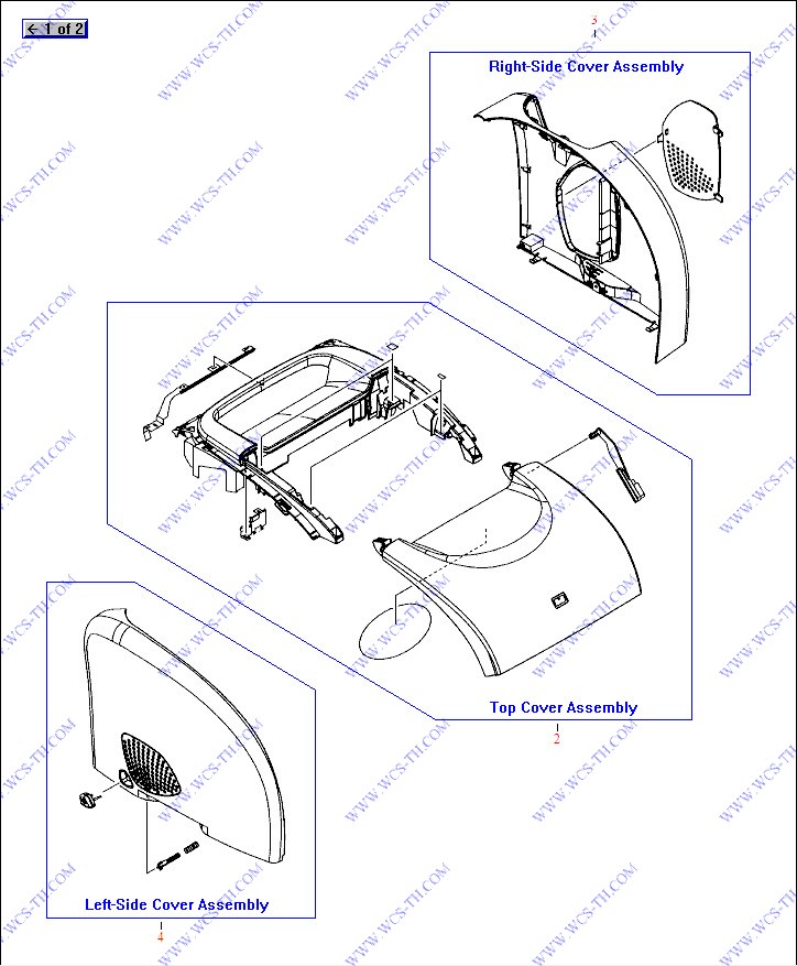
External Covers
| Pic No. | Parts ID | Parts Name | Link |
| 2 | RB3-0030-000CN | Upper rear cover (Quartz Gray) - Mounts on the upper rear of the printer above the face-up output tray door | Find 2 |
| 3 | RB3-0035-000CN | Interface bezel (Quartz Gray plastic) - Vertical cover that surronds the interface connectors | Find 3 |
| 4 | RB3-0032-000CN | Face-down paper output L-Shaped cover ( Blue) - Serves as the rear of the tray for the face-down output tray on top of the printer | Find 4 |
| 5 | RB3-0033-000CN | Memory access door (Quartz Gray perforated plastic) - Allows access to the printer memory slots - Mounts on the right side cover | Find 5 |
| 6 | RG5-6927-000CN | Control panel assembly (mechanical only) - Includes the |Rotate Carousel|, |Cancel Job| and the |Go| buttons, plus the various indicator light pipes - All switches and LED|s are on the formatter PC board | Find 6 |
| 7 | RS6-2759-000CN | Compression spring | Find 7 |
| 8 | RB3-0037-000CN | Power switch rod - Goes between the power button and the power switch on the low voltage power supply board | Find 8 |
| 11 | RB3-0089-000CN | Top cover rack arm (Black) - Plastic arm with teeth on bottom edge - Disengages the imaging drum/transfer assembly drive cams when the top door is open | Find 11 |
| 11 | RB3-0089-030CN | Top cover rack arm (Black) - Plastic arm with teeth on bottom edge - Disengages the imaging drum/transfer assembly drive cams when the top door is open | Find 11 |
| 12 | RF5-4007-000CN | Top cover door (blue plastic) - For accessing the toner cartridges and the imaging drum/transfer assembly - Mounts to the top cover frame | Find 12 |
| 13 | RB3-0028-000CN | Left side cover (Quartz Gray) - Does not include any attaching parts | Find 13 |
External Covers (Assemblies)
| Pic No. | Parts ID | Parts Name | Link |
| 2 | RG5-6900-000CN | Top cover assembly (blue plastic) - Includes the molded-in face-down output tray and the lift-up top cover door assembly | Find 2 |
| 3 | RG5-6953-000CN | Right side cover assembly (Quartz Gray) plastic - Includes the DIMM memory door | Find 3 |
| 4 | RG5-6902-000CN | Left side cover assembly (Quartz Gray) plastic - Includes the power switch button, rod and spring (The power switch is located on the low voltage power supply board) | Find 4 |
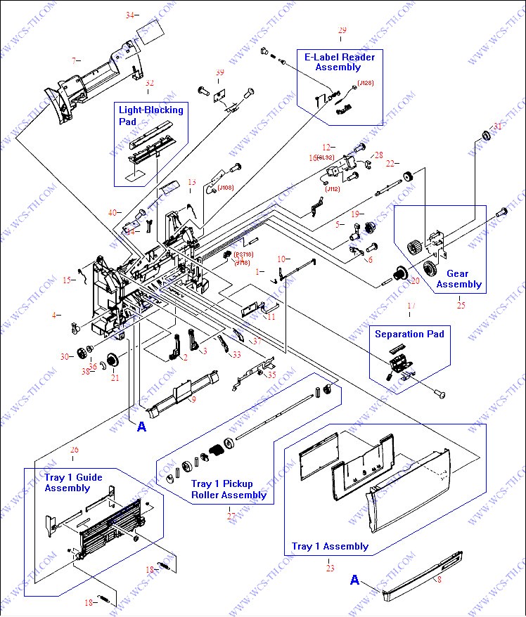
Front Frame Assembly
| Pic No. | Parts ID | Parts Name | Link |
| 1 | RB2-9952-000CN | Tray 1 flag spring - Provides torsion for the tray 1 paper sensor flag | Find 1 |
| 2 | RB2-6405-000CN | Tray hinge - For the left side of the multi-purpose front input tray (Tray 1) | Find 2 |
| 2 | RB2-3041-020CN | Tray hinge - For the left side of the multi-purpose front input tray (Tray 1) | Find 2 |
| 2 | RB2-3041-000CN | Tray hinge - For the left side of the multi-purpose front input tray (tray one) | Find 2 |
| 3 | RB2-3042-000CN | Tray hinge - For the right side of the multi-purpose front input tray (tray one) | Find 3 |
| 3 | RB2-6406-000CN | Tray hinge - For the right side of the multi-purpose front input tray (Tray 1) | Find 3 |
| 3 | RB2-3042-020CN | Tray hinge - For the right side of the multi-purpose front input tray (Tray 1) | Find 3 |
| 4 | RB2-3043-000CN | Left roller bushing - Acts as the bearing and retainer for the left end of the paper pickup roller assembly (tray 1) | Find 4 |
| 5 | RB2-3044-000CN | Right roller bushing - Acts as the bearing and retainer for the right end of the paper pickup roller assembly (tray 1) | Find 5 |
| 6 | RB2-6248-000CN | Damper assembly (Gray plastic piece with small 13-tooth gear on it) | Find 6 |
| 7 | RB3-0102-000CN | Front inner cover (Blue) - Mounts on the front frame above the multi-purpose input tray | Find 7 |
| 8 | RB3-0103-000CN | Front lower cover (blue plastic) - Front lower strip below the multi-purpose input tray - Has recessed area for the printer logo | Find 8 |
| 9 | RB3-0104-000CN | Roller cover - Covers the multipurpose paper pickup roller assembly - Mounts on the lower front of the front frame assembly | Find 9 |
| 10 | RB3-0111-000CN | Paper flag - Plastic rod with paper sensing flag on one end and sensor activator flag on the other | Find 10 |
| 11 | RB3-0119-000CN | Grounding plate | Find 11 |
| 12 | RB3-0120-020CN | Solenoid cover (Steel) - For magnetic wave sheilding - Mounts over the solenoid on the right side of the front frame assembly | Find 12 |
| 12 | RB3-0120-000CN | Solenoid cover (Steel) - For magnetic wave sheilding | Find 12 |
| 13 | RB3-0121-000CN | Right retaining spring - Helps to secure and ground the imaging drum/transfer assembly in the printer | Find 13 |
| 14 | RB3-0135-000CN | Test print flag (Black lever) | Find 14 |
| 15 | RB3-0122-000CN | Left retaining spring - Helps to secure the imaging drum/transfer assembly in the printer | Find 15 |
| 16 | RH7-5337-000CN | Solenoid assembly | Find 16 |
| 17 | RF5-4012-000CN | Separation pad assembly - Includes the separation pad, holder and spring | Find 17 |
| 18 | RS6-2030-000CN | Tension spring | Find 18 |
| 19 | RS7-0418-000CN | 26 tooth gear (Black plastic) - Has 1/8th portion of gear cut away | Find 19 |
| 20 | RS7-0424-000CN | Dual gear - 20 tooth / 40 tooth | Find 20 |
| 21 | RS7-0426-000CN | Dual gear - 26 tooth / 50 tooth (White plastic) | Find 21 |
| 22 | RS7-0429-000CN | 26 tooth gear (White plastic) - Has recess for shaft drive pin | Find 22 |
| 23 | RG5-6937-000CN | Multi-purpose front input tray assembly (tray-1) - Includes the front cover piece, pull-out paper support, and the flip-out extender | Find 23 |
| 24 | WG8-5593-000CN | Sensor PC board - Small board with flag activated photosensor | Find 24 |
| 24 | WG8-5382-000CN | Sensor PC board - Small board with flag activated photosensor | Find 24 |
| 25 | RG5-6938-000CN | Gear assembly - Metal plate with two white plastic gears attached | Find 25 |
| 25 | RG5-6938-030CN | Gear assembly - Metal plate with two white plastic gears attached | Find 25 |
| 26 | RG5-6951-000CN | Paper guide assembly - Paper width adjustable guide assembly for the multi-purpose front input tray (tray 1) | Find 26 |
| 27 | RG5-6952-020CN | Paper pickup roller assembly - Includes the shaft, guide assembly cams, the D-shaped roller, and roller retainers - Picks paper from the multipurpose front input tray (tray 1) - Mounts in the lower portion of the front frame assembly | Find 27 |
| 27 | RB3-0160-000CN | Paper pickup roller (|D| shaped) | Find 27 |
| 27 | RG5-6952-000CN | Paper pickup roller assembly - Includes the shaft, guide assembly cams, the D-shaped roller, and roller retainers - Picks paper from the multipurpose front input tray (tray 1) | Find 27 |
| 28 | WT2-5056-000CN | Cable clip - |C| shaped White plastic | Find 28 |
| 29 | RG5-6956-000CN | E-label reader (contact board only) - Connects the cartridge non-volitale memory to the DC controller board | Find 29 |
| 29 | RG5-7131-000CN | E-label reader (contact board only) - Connects the cartridge non-volitale memory to the DC controller board | Find 29 |
| 29 | RG5-6957-000CN | E-label reader assembly - Connects cartridge non-volatile memory to the DC controller board | Find 29 |
| 29 | RG5-7132-000CN | E-label reader assembly - Connects cartridge non-volatile memory to the DC controller board | Find 29 |
| 30 | RS7-0425-000CN | 30 tooth gear (White plastic) | Find 30 |
| 31 | RS5-1635-000CN | Shaft bushing | Find 31 |
| 32 | RF5-4047-000CN | Light blocking pad assembly - Black plastic frame with soft rubber gasket and stiff conductive Mylar piece (grounded) | Find 32 |
| 33 | RB2-9954-000CN | Left paper feed guide (small Black plastic arm) | Find 33 |
| 34 | RS6-8662-000CN | Image cartridge label - Shows the imaging drum/transfer assembly removal steps | Find 34 |
| 35 | RB2-9942-000CN | Grounding plate - Provides grounding for the top-of-page sensor and shielding for the density sensor boards | Find 35 |
| 36 | RS5-1638-000CN | Bushing | Find 36 |
| 37 | RB2-9955-000CN | Right paper feed guide (small Black plastic arm) | Find 37 |
| 38 | XD2-1100-502CN | E-ring clip | Find 38 |
| 39 | RG5-7612-000CN | Top of page photoelectric sensor PC board - Includes the photoelectric top of page sensor and the print engine test switch | Find 39 |
| 39 | RG5-6966-000CN | Top of page photoelectric sensor PC board - Includes the photoelectric top of page sensor and the print engine test switch | Find 39 |
| 40 | RH7-7158-000CN | Density photoelectric sensor PC board | Find 40 |
| 40 | RH7-7146-000CN | Density photoelectric sensor PC board | Find 40 |
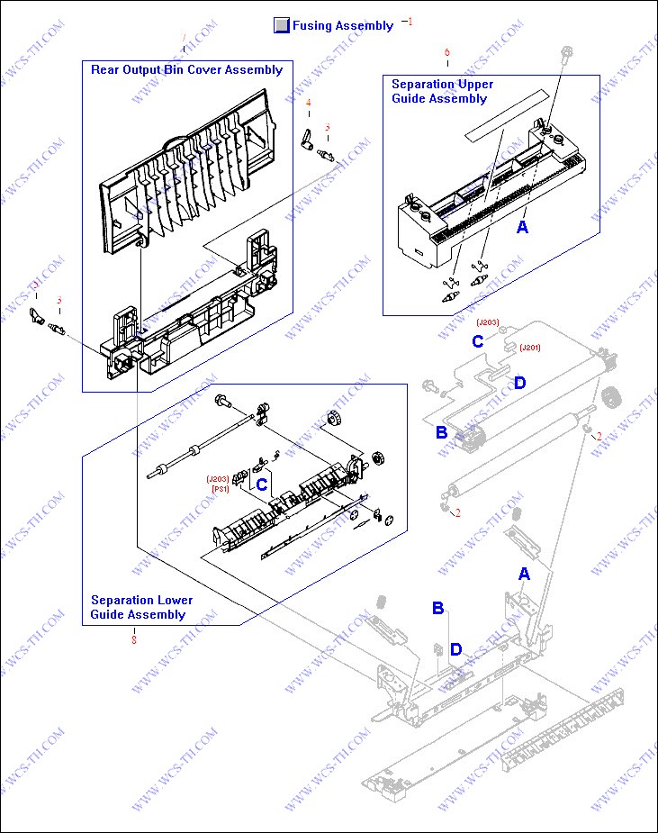
Fusing Assembly
| Pic No. | Parts ID | Parts Name | Link |
| 1 | RG5-6913-000CN | Fusing assembly (For 220V to 240V operation) - Bonds the toner to the paper with heat | Find 1 |
| 1 | RG5-6903-000CN | Fusing assembly (For 110V to 127V operation) - Bonds the toner to the paper with heat | Find 1 |
| 1 | RM1-3525-000CN | Fusing assembly (For 220V to 240V operation) - Bonds the toner to the paper with heat - Slides in and locks in lower rear of printer | Find 1 |
| 2 | RB2-2973-000CN | Support bushing | Find 2 |
| 3 | RB2-4933-000CN | Lock release shaft - Small shaft with locking tab - Does NOT include the lock release lever | Find 3 |
| 4 | RB3-0178-000CN | Right side lock release lever | Find 4 |
| 5 | RB3-0179-000CN | Left side lock release lever | Find 5 |
| 6 | RG5-6929-000CN | Separation guide assembly - Includes the plastic guide, label, and the two small spring loaded rollers | Find 6 |
| 7 | RG5-6931-000CN | Face-up output tray assembly - Includes the pull-down door and fusing assembly locking bracket (Does NOT include the lock releases) | Find 7 |
| 7 | RB3-0176-000CN | Face-Up output tray door (ONLY) | Find 7 |
| 8 | RG5-6930-000CN | Lower separation guide assembly - Includes the guide bracket, paper output sensor (PS1) and flag, exit drive shaft with two rubber rollers, shaft gear, and idler gear | Find 8 |
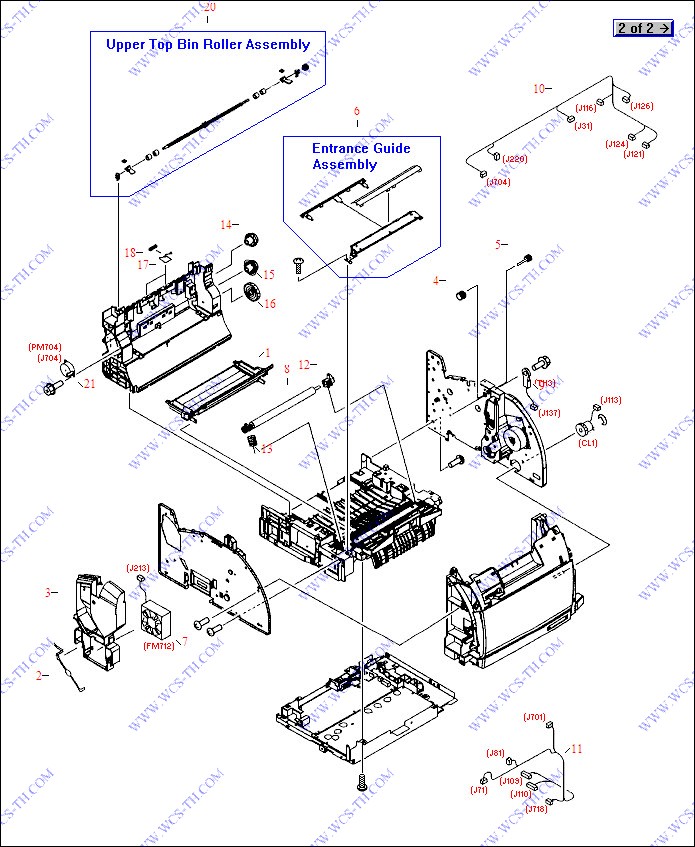
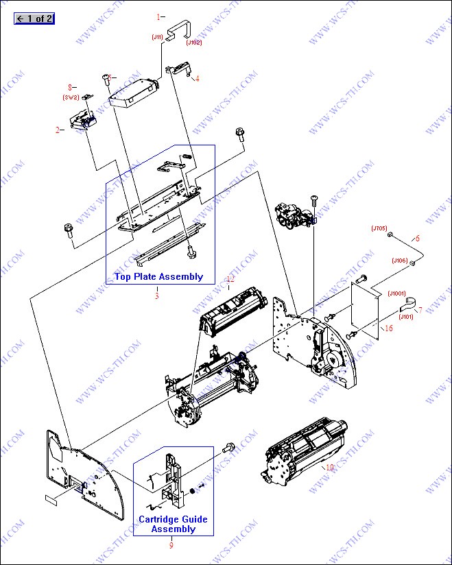
Internal Components (1 of 2)
| Pic No. | Parts ID | Parts Name | Link |
| 1 | RB3-0019-000CN | Toner catch tray (curved Black plastic piece) - Holds residual toner from photosensitive drum | Find 1 |
| 2 | RB2-9932-000CN | RFI shield - Parallel wire form mounted over the fan | Find 2 |
| 3 | RB3-0025-000CN | Airflow guide (duct) / fan holder bracket assembly (Quartz Gray plastic) | Find 3 |
| 4 | RB3-0091-000CN | 16 tooth gear (Black plastic) - Gear with large stop tooth and shaft lock tab | Find 4 |
| 5 | RB3-0092-000CN | 15 tooth gear with drive shaft (Black plastic) | Find 5 |
| 6 | RF5-4049-000CN | Entrance guide assembly - Angled metal guide between the registration roller and the transfer roller | Find 6 |
| 7 | RH7-1630-000CN | Cooling fan (Panaflo Model FBA08T24H - 80mm X 80mm X 15mm high, DC brushless, 24V DC, 190mA) | Find 7 |
| 7 | RH7-1537-000CN | Cooling fan (Panaflo Model FBA08T24H - 80mm X 80mm X 15mm high, DC brushless, 24V DC, 190mA) | Find 7 |
| 8 | RF5-4040-020CN | Transfer roller assembly - Long black foam type roller - Transfers static charge to paper | Find 8 |
| 9 | RH7-7159-000CN | Thermistor | Find 9 |
| 9 | RH7-7149-000CN | Thermistor | Find 9 |
| 10 | RG5-7144-000CN | Cable assembly (with seven connectors) | Find 10 |
| 11 | RG5-7145-000CN | Front cable assembly (six connectors) | Find 11 |
| 12 | RB3-0014-000CN | Bushing assembly (black plastic bushing with small guide roller on top) | Find 12 |
| 13 | RB3-0015-000CN | Compression spring | Find 13 |
| 14 | RS7-0435-000CN | Dual gear - 32 tooth / 37 tooth (White plastic) | Find 14 |
| 15 | RS7-0436-000CN | Dual gear - 37 tooth / 43 tooth (White plastic) | Find 15 |
| 16 | RS7-0437-000CN | 51 tooth gear (White plastic) | Find 16 |
| 17 | RB2-9905-000CN | Torsion spring | Find 17 |
| 18 | RB2-9908-000CN | Pressure roller (small Black hard plastic disk shaped roller) | Find 18 |
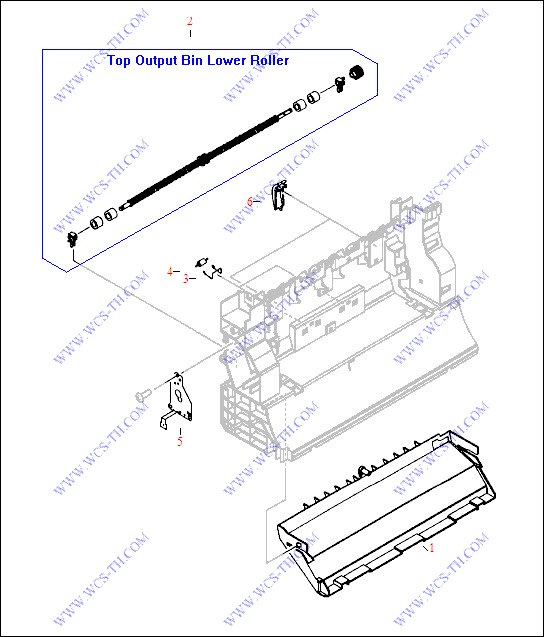
| 20 | RG5-6897-020CN | Upper top bin output roller assembly - Includes the shaft with four rubber rollers, two bushing/shaft retainers, two anti-reversing flaps, and the drive gear | Find 20 |
| 20 | RG5-6897-000CN | Upper top bin output roller assembly - Includes the shaft with four rubber rollers, two bushing/shaft retainers, two anti-reversing flaps, and the drive gear | Find 20 |
| 21 | RH7-1533-000CN | Stepping motor - 24VDC | Find 21 |
| 21 | RH7-1629-000CN | Stepping motor - 24VDC | Find 21 |
Internal Components (2 of 2)
| Pic No. | Parts ID | Parts Name | Link |
| 1 | RH2-5524-000CN | Flat flexible cable (FFC) assembly | Find 1 |
| 2 | RB3-0023-000CN | Interlock switch holder (Quartz Gray plastic) - Does NOT include the micro-switch | Find 2 |
| 3 | RG5-6907-030CN | Laser/scanner support assembly (sheet metal plate) | Find 3 |
| 3 | RG5-6907-000CN | Laser/scanner support assembly (sheet metal plate) | Find 3 |
| 4 | RB2-9903-000CN | Cable guide (Quartz Gray plastic) | Find 4 |
| 5 | RG5-6880-000CN | Laser/scanner assembly | Find 5 |
| 5 | RG5-6890-030CN | Laser/scanner assembly | Find 5 |
| 6 | RG5-7114-000CN | Cable assembly (two 4-pin connectors) with shield | Find 6 |
| 6 | RG5-7114-020CN | Cable assembly (two 4-pin connectors) with shield - Connects between the cartridge drive motor and the DC controller board | Find 6 |
| 7 | C9706-60104 | Flat flexible cable | Find 7 |
| 8 | RH7-6051-000CN | Microswitch with lever activator | Find 8 |
| 9 | RG5-6935-000CN | Left cartridge guide assembly | Find 9 |
| 9 | RG5-6935-020CN | Left cartridge guide assembly | Find 9 |
| 10 | C9704A | Imaging drum/transfer assembly cartridge - Inserts into printer through the top door - Life expectancy is 20,000 pages for black print only, 5,000 pages for color (Typical combined life is approximately 6,000 to 8,000 pages) | Find 10 |
| 10 | C9704-67901 | Imaging drum/transfer assembly cartridge - Inserts into printer through the top door - Life expectancy is 20,000 pages for black print ONLY, 5,000 pages for color (Typical combined life is approximately 6,000 to 8,000 pages) | Find 10 |
| 12 | C9700A | HP Color LaserJet smart Black print cartridge - Will print approximately 5,000 pages at 5% coverage | Find 12 |
| 12 | C9701A | HP Color LaserJet smart Cyan print cartridge - Will print approximately 5,000 pages at 5% coverage | Find 12 |
| 12 | C9702A | HP Color LaserJet smart Yellow print cartridge - Will print approximately 5,000 pages at 5% coverage | Find 12 |
| 12 | C9703A | HP Color LaserJet smart Magenta print cartridge - Will print approximately 5,000 pages at 5% coverage | Find 12 |
| 12 | C9700-67901 | HP Color LaserJet smart Black print cartridge - Will print approximately 5,000 pages at 5% coverage | Find 12 |
| 12 | C9701-67901 | HP Color LaserJet smart Cyan print cartridge - Will print approximately 5,000 pages at 5% coverage | Find 12 |
| 12 | C9703-67901 | HP Color LaserJet smart Magenta print cartridge - Will print approximately 5,000 pages at 5% coverage | Find 12 |
| 12 | C9702-67901 | HP Color LaserJet smart Yellow print cartridge - Will print approximately 5,000 pages at 5% coverage | Find 12 |
| 16 | C9705-69003 | DC controller board | Find 16 |
Main Drive Assembly

| Pic No. | Parts ID | Parts Name | Link |
| 1 | RG5-6932-060CN | Right side plate assembly - Includes the front half of the metal frame assembly, gears, imaging drum/transfer assembly drive cams, cover engaging mechanism, roller engaging clutch (CL2), and main drive motor (DCM701) | Find 1 |
| 1 | RG5-6932-070CN | Right side plate assembly - Includes the front half of the metal frame assembly, gears, imaging drum/transfer assembly drive cams, cover engaging mechanism, roller engaging clutch (CL2), and main drive motor (DCM701) - Mounts on the right side | Find 1 |
| 2 | RF5-4010-000CN | Main motor assembly - Large motor mounted on a controller PC board | Find 2 |
| 2 | RF5-4010-020CN | Main motor assembly - Large motor mounted on a controller PC board - Mounts on the inside of the metal right side frame assembly | Find 2 |
| 3 | RH7-5366-000CN | Electromagnetic clutch assembly (24V) - Electrical clutch between the clutch drive gear and shaft | Find 3 |
| 3 | RH7-5389-000CN | Electromagnetic clutch assembly (24V) - Electrical clutch between the clutch drive gear and shaft | Find 3 |
| 4 | RB3-0090-000CN | Rack slide - White plastic piece with gear teeth layed out in rack form on both sides | Find 4 |
| 5 | RG5-7115-000CN | Cable assembly (two 3-pin connectors) | Find 5 |
| 6 | RG5-6934-000CN | Right rear side plate assembly - Includes the rear half of the metal right side plate, the fusing assembly drive motor and the three associated gears | Find 6 |
Major Assembly Locator

| Pic No. | Parts ID | Parts Name | Link |
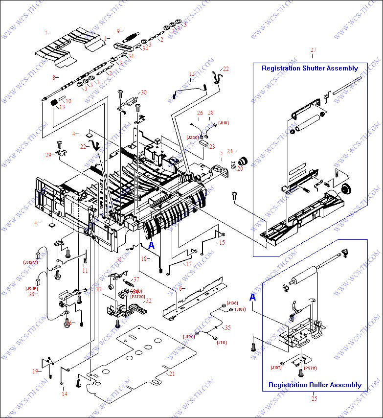
Middle Frame Assembly
| Pic No. | Parts ID | Parts Name | Link |
| 1 | RB1-8668-030CN | Feed guide drive belt - Small belt approximately 5/16 inch wide with |A| shaped ribs on it | Find 1 |
| 2 | RB3-0061-000CN | Pulley roller (accommodates three feed belts) - Small black roller approximately 3.49cm (1-3/4 inches) long with three ball type pulleys | Find 2 |
| 3 | RB3-0063-000CN | Paper feed belt - Small black rubber belt approximately 1/8 inch wide with little |A| shaped ribs on it | Find 3 |
| 4 | RB2-6297-000CN | Rubber foot - Square self-adhesive rubber foot | Find 4 |
| 5 | RB3-0286-000CN | Contact plate | Find 5 |
| 6 | RB3-0009-000CN | Static eliminator ground plate - Right angled metal piece with small teeth on top edge | Find 6 |
| 7 | RB3-0010-000CN | Feed plate - Center metal plate with slots that the ribs on the middle frame assembly go through | Find 7 |
| 7 | RB3-0010-030CN | Feed plate - Center metal plate with slots that the ribs on the middle frame assembly go through | Find 7 |
| 8 | RB3-0011-000CN | Feed drive shaft - Long shaft with eight feed belt ball type pulleys and one ribbed feed guide drive belt pulley | Find 8 |
| 9 | RB3-0012-000CN | Belt roller - Small oval shaped roller approximately 1-3/4 inches long | Find 9 |
| 10 | RB3-0060-020CN | Idler gear shaft - Short metal rod | Find 10 |
| 10 | RB3-0060-000CN | Idler gear shaft - Short metal rod | Find 10 |
| 11 | RB3-0045-000CN | Electrical contact spring | Find 11 |
| 12 | RB3-0016-000CN | Electrical contact spring - Spring steel wire with compression springs formed on both ends | Find 12 |
| 13 | RB3-0022-000CN | 22 tooth gear (Black plastic) - Small gear with diagonally cut teeth | Find 13 |
| 14 | RB3-0042-000CN | Electrical contact spring | Find 14 |
| 15 | RB3-0043-000CN | Electrical contact spring | Find 15 |
| 16 | RB3-0044-000CN | Electrical contact spring | Find 16 |
| 17 | RB3-0046-000CN | Electrical contact spring | Find 17 |
| 18 | RB3-0047-000CN | Electrical contact spring | Find 18 |
| 19 | RB3-0048-000CN | Electrical contact spring | Find 19 |
| 20 | RS5-1637-000CN | Bushing (black plastic) | Find 20 |
| 21 | RB3-0056-000CN | Insulating sheet (Transparent plastic) | Find 21 |
| 22 | RB3-0057-000CN | Transfer slide plate - Small |U| shaped metal insert plates | Find 22 |
| 23 | RH2-5519-000CN | Connector assembly - For optional paper tray | Find 23 |
| 23 | WS1-6336-000CN | Connector assembly - For optional paper tray | Find 23 |
| 24 | RS7-0428-000CN | 30 tooth gear (White plastic) | Find 24 |
| 25 | RG5-6939-020CN | Registration roller assembly - Includes the roller, bushings, mounting plate, paper sensor, and the sensor flag | Find 25 |
| 25 | RG5-6939-000CN | Registration roller assembly - Includes the roller, bushings, mounting plate, paper sensor, and the sensor flag | Find 25 |
| 26 | RG5-7123-000CN | Grounding cable assembly | Find 26 |
| 27 | RG5-6940-050CN | Registration shutter assembly - Includes the metal roller, mounting frame, grounding springs, and the dual coupling gear | Find 27 |
| 27 | RG5-6940-000CN | Registration shutter assembly - Includes the metal roller, mounting frame, grounding springs, and the dual coupling gear | Find 27 |
| 28 | RG5-7122-000CN | Cable assembly - |Y| type cable (three connectors) - The 14-pin connector splits into an 8-pin connector and a 6-pin connector | Find 28 |
| 29 | RB3-0052-000CN | Gear Cover (Small Black plastic cover) - Covers the left end of the feed drive shaft | Find 29 |
| 30 | RB3-0065-000CN | Contact plate - copper clad metal spring - Holds the left end of the small 500 Meg-ohm resistor | Find 30 |
| 31 | RB2-9925-000CN | Sensor arm and flag - Activates the photosensor (Does NOT include the roller) | Find 31 |
| 32 | RB2-9924-000CN | Sensor assembly mounting holder | Find 32 |
| 33 | RB2-7195-000CN | Sensor flag roller (small White plastic roller) | Find 33 |
| 34 | RB3-0067-000CN | Pulley roller (accommodates one feed belt) - Small black roller approximately 1.59cm (5/8 inch) long with one ball type pulley | Find 34 |
| 35 | RG5-7128-000CN | Cable assembly (four 3-pin connectors) | Find 35 |
| 36 | WG8-5382-000CN | Sensor PC board - Small board with flag activated photosensor | Find 36 |
| 36 | WG8-5593-000CN | Sensor PC board - Small board with flag activated photosensor | Find 36 |
| 37 | RS6-2766-000CN | Tension spring | Find 37 |
| 38 | RG5-7130-000CN | High voltage cable assembly | Find 38 |
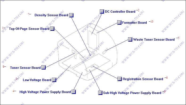
PC Board Assembly Locator
| Pic No. | Parts ID | Parts Name | Link |
| 1 | RG5-6966-000CN | Top of page photoelectric sensor PC board - Includes the photoelectric top of page sensor and the print engine test switch | Find 1 |
| 1 | RG5-7612-000CN | Top of page photoelectric sensor PC board - Includes the photoelectric top of page sensor and the print engine test switch | Find 1 |
| 2 | C9705-69003 | DC controller board | Find 2 |
| 3 | RH3-2241-000CN | Low voltage power supply - For 110V to 127V AC operation - Includes the AC power input connector and power switch | Find 3 |
| 3 | RH3-2243-000CN | Low voltage power supply - For 220V to 240V AC operation - Includes the AC power input connector and power switch | Find 3 |
| 4 | RG5-6960-000CN | High voltage power supply board (HVT) assembly - Has contacts for the eight high voltage springs in the printer | Find 4 |
| 5 | RG5-6965-000CN | Waste toner sensor PC board - Small board with an LED and photoelectric sensor - Monitors the level of the excess toner deposited in the imaging drum/transfer assembly | Find 5 |
| 6 | RG5-7613-000CN | Registration sensor PC Board - Small board with flag activated photosensor | Find 6 |
| 6 | RG5-6967-000CN | Registration sensor PC Board - Small board with flag activated photosensor | Find 6 |
| 7 | RH7-7158-000CN | Density photoelectric sensor PC board | Find 7 |
| 7 | RH7-7146-000CN | Density photoelectric sensor PC board | Find 7 |
| 8 | RG5-7609-000CN | Carousel position and toner level photoelectric sensor PC board - |L| Shaped PC board with the two sensors | Find 8 |
| 8 | RG5-6964-000CN | Carousel position and toner level photoelectric sensor PC board - |L| Shaped PC board with the two sensors | Find 8 |
| 9 | RG5-7124-000CN | Sub-high voltage board - Small auxillary PC board | Find 9 |
| 9 | RG5-7616-000CN | Sub-high voltage board - Small auxillary PC board | Find 9 |
| 10 | C9145-69001 | Formatter board assembly - Includes the formatter board and all the metal cage covers | Find 10 |
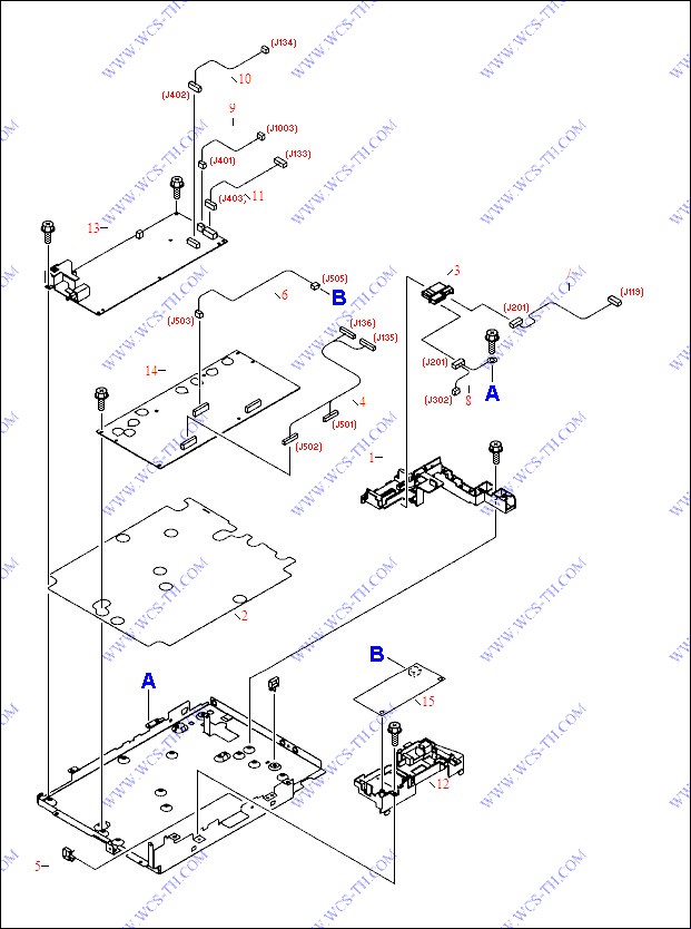
Power Supply Base Assembly
| Pic No. | Parts ID | Parts Name | Link |
Rear Frame Assembly
| Pic No. | Parts ID | Parts Name | Link |
| 1 | RB2-9904-000CN | Airflow Guide (duct) - Black plastic insert piece which runs the width of the printer and has an air flow hole on right side | Find 1 |
| 2 | RG5-6936-000CN | Lower top bin output roller assembly - Includes the shaft with four rubber rollers, two bushing/shaft retainers, and the drive gear | Find 2 |
| 3 | RB2-9906-000CN | Torsion spring | Find 3 |
| 4 | RB2-9909-000CN | Pressure roller (small Black hard plastic |solid| roller) | Find 4 |
| 5 | RB2-9916-020CN | Cover - For the engaging motor (PM704) - Mounts on the upper left side of the rear frame assembly | Find 5 |
| 5 | RB2-9916-000CN | Cover - For fuser motor | Find 5 |
| 6 | RB2-9912-000CN | Top output bin guide - Small curved ribbed black plastic piece | Find 6 |
Toner Cartridge Carousel Assembly
| Pic No. | Parts ID | Parts Name | Link |
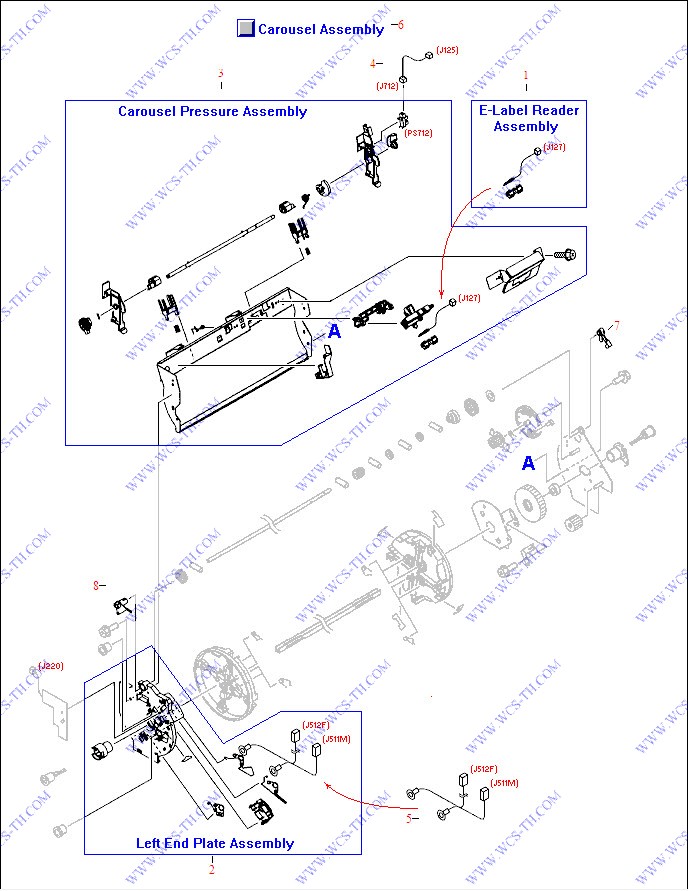
| 1 | RG5-7132-000CN | E-label reader assembly - Connects cartridge non-volatile memory to the DC controller board | Find 1 |
| 1 | RG5-6974-000CN | Cable assembly | Find 1 |
| 1 | RG5-6957-000CN | E-label reader assembly - Connects cartridge non-volatile memory to the DC controller board | Find 1 |
| 2 | RG5-6942-000CN | Left side carousel plate assembly - End plate under the rotational toner cartridge carousel - Includes all of the high voltage contacts for the toner cartridges | Find 2 |
| 2 | RG5-6942-030CN | Left side carousel plate assembly - End plate under the rotational toner cartridge carousel - Includes all of the high voltage contacts for the toner cartridges - Mounts on the metal carousel support frame | Find 2 |
| 3 | RG5-6943-020CN | Carousel pressure (support) assembly - Includes the main rear support, E-label reader assembly, engaging sensor, and the engaging rod shaft - Primary support structure for the toner cartridge carousel | Find 3 |
| 3 | RG5-6943-000CN | Carousel pressure (support) assembly - Includes the main rear support, E-label reader assembly, engaging sensor, and the engaging rod shaft | Find 3 |
| 4 | RG5-7117-000CN | Cable assembly (two 3-pin connectors) | Find 4 |
| 5 | RG5-7129-000CN | Cable assembly (two connectors and two spade lugs) | Find 5 |
| 6 | RG5-6910-080CN | Carousel (Rotary) assembly - Includes the carousel assembly, the support assembly, end plates, drive gears and shaft, sensors, and cables | Find 6 |
| 7 | RB2-9808-000CN | Bushing/shaft retainer assembly - Black plastic | Find 7 |
| 8 | RB2-9809-000CN | Bushing/shaft retainer assembly (White plastic) | Find 8 |
Toner Cartridge Carousel Drive Assembly

| Pic No. | Parts ID | Parts Name | Link |
| 1 | RG5-6911-000CN | Rotary drive assembly - Includes the carousel rotating motor (DCM703), toner cartridge drive motor (PM705), developing rotary stopper solenoid (SL93), bracket, and gears | Find 1 |
| 2 | RG5-6958-000CN | Rotary motor assembly | Find 2 |
| 3 | RH7-1535-000CN | Stepping motor - 24VDC | Find 3 |
| 3 | RH7-1625-000CN | Stepping motor - 24VDC | Find 3 |
| 4 | RH7-5340-000CN | SOLENOID | Find 4 |
| 4 | RH7-5384-000CN | Solenoid assembly | Find 4 |