คุณยังไม่มีสินค้าในรถเข็น

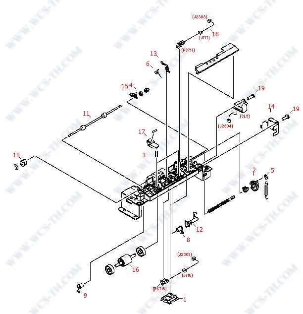
250 Sheet Tray - Center Frame Assembly
| Pic No. | Parts ID | Parts Name | Link |
| 1 | RB3-0166-000CN | Bottom inner cover (Black) plastic - One covers the paper feed sensor in the center and the other covers sensor wires toward the right side - Mounts on the bottom of the center frame assembly of the 250-sheet input tray assembly (two used) | Find 1 |
| 2 | RS7-0430-000CN | 26 tooth gear - White gear with 1/8th portion of gear cut away and pin for spring tensioning - Mounts on the end of the paper pickup roller in the base on the 250-sheet input tray assembly | Find 2 |
| 3 | RS6-2760-000CN | Compression spring - Provides pressure for the pressure rollers on the center frame assembly (two used) - For the base on the 250-sheet input tray assembly | Find 3 |
| 4 | RS5-1636-000CN | Shaft bushing - Mounts on the gear end of the feed roller shaft in the base on the 250-sheet input tray assembly | Find 4 |
| 5 | RB1-2190-000CN | Pickup roller spring hook - Clips on the pin of the drive gear for the pickup roller and hooks the tensioning spring - For the base on the 250-sheet input tray assembly | Find 5 |
| 6 | RB9-0843-000CN | Torsion spring - Provides a small amount of back pressure for the paper sensor flag - For the base on the 250-sheet input tray assembly | Find 6 |
| 7 | WG8-5593-000CN | Sensor PC board - Small board with flag activated photosensor - (PS718) Detects paper from the multipurpose input tray, mounts on the right side of the front frame assembly - (PS720) Front of page sensor for the fusing assembly, mounts on the underside of | Find 7 |
| 8 | RB9-0834-000CN | Shaft bushing/retainer - Right side pickup roller support bushing - Mounts on and retains the right end of the pickup roller shaft - For the base on the 250-sheet input tray assembly | Find 8 |
| 9 | RB9-0835-000CN | Shaft bushing/retainer - Left side pickup roller support bushing - Mounts on and retains the left end of the pickup roller shaft - For the base on the 250-sheet input tray assembly | Find 9 |
| 10 | RS5-1638-000CN | Bushing - For the registration roller gear drive shaft on the right side of the front frame assembly, and the left side of the feed roller in the 250-sheet paper input tray assembly | Find 10 |
| 11 | RB3-0129-020CN | Feed roller assembly - Includes the metal shaft and two small rubber rollers - Feeds paper from the paper cassette (or tray three below) into the printer - Mounts on the top of the center frame in the base on the 250-sheet input tray assembly | Find 11 |
| 12 | RB3-0130-000CN | Shaft mounted sensor flag (black plastic) - For the paper out sensor - Mounts on the paper pickup roller drive shaft - For the base on the 250-sheet input tray assembly | Find 12 |
| 13 | RB3-0132-000CN | Mechanical sensor flag (black plastic) - For the paper feed sensor - Mounts on top of the center frame assembly - For the base on the 250-sheet input tray assembly | Find 13 |
| 14 | RB3-0136-020CN | Solenoid cover/magnetic shield - Mounts on the right end of the center frame assembly (over the pickup solenoid) - For the base on the 250-sheet input tray assembly | Find 14 |
| 15 | RB3-0137-000CN | Grounding plate - Grounds the paper feed roller - Mounts towards the right end of the center frame assembly - For the base on the 250-sheet input tray assembly | Find 15 |
| 16 | RB3-0161-000CN | Paper pickup roller assembly - Includes the |D| shaped rubber roller on a plastic shaft - Mounts in the lower center of the center frame assembly - For the base on the 250-sheet input tray assembly | Find 16 |
| 17 | RF5-4035-000CN | Pressure roller and arm assembly - Includes the small white roller, the holding arm, and roller scraper - Rolls against the rubber feed rollers (two used) - For the base on the 250-sheet input tray assembly | Find 17 |
| 18 | RG5-7138-000CN | Cable assembly - From sensor (PS717) (which senses paper feeding from optional tray 3) to the small interconnecting PC board on the right side frame/cover assembly - For the base on the 250-sheet input tray assembly | Find 18 |
| 19 | XB4-7401-005CN | M4 pan-head phillips screw with self-tapping threads - 10mm long | Find 19 |
250 Sheet Tray - External Covers

| Pic No. | Parts ID | Parts Name | Link |
| 1 | RG5-7635-000CN | 250-sheet paper cassette tray assembly (complete) - Pull out cassette that the paper is loaded into - Does NOT include the paper feed base assembly | Find 1 |
| 2 | RG5-7634-000CN | Right side support frame/cover assembly - Includes the frame/cover, printer interface connector, cable, feed drive PC board, and snap-on lid - For the base on the 250-sheet input tray assembly | Find 2 |
| 3 | RB3-1168-000CN | Left side support frame/cover assembly - For the base on the 250-sheet input tray assembly | Find 3 |
| 4 | RB3-0108-020CN | Metal support cross-brace - Mounts on the top rear of the left and right support frame/cover assemblies - For the base on the 250-sheet input tray assembly | Find 4 |
| 5 | RB3-0282-000CN | Inner cover - Covers the small interconnecting PC board - Mounts on top of the right side support frame/cover assemly on the base of the 250-sheet feeder assembly | Find 5 |
| 6 | RB3-0283-000CN | Inner cover - Covers the bottom of the connector that interconnects the input tray base to the printer - Mounts on the bottom of the right side support frame/cover assembly for the base of the 250-sheet tray assembly | Find 6 |
| 7 | RB2-6297-000CN | Rubber foot - Square self-adhesive rubber foot - Attaches to the rear of the middle frame assembly (two used) | Find 7 |
| 8 | XB4-7401-005CN | M4 pan-head phillips screw with self-tapping threads - 10mm long | Find 8 |
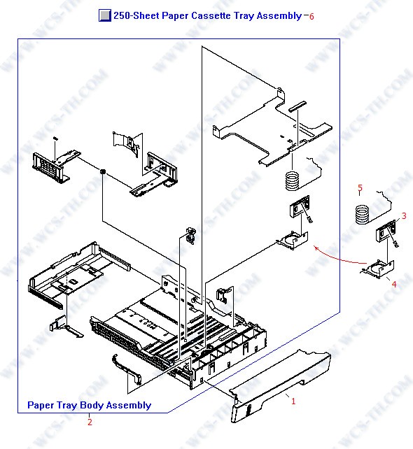
250 Sheet Tray - Paper Cassette Tray
| Pic No. | Parts ID | Parts Name | Link |
| 1 | RB3-1170-000CN | Front cover - Mounts on the front of the cassette assembly for the 250-sheet input tray assembly | Find 1 |
| 2 | RG5-7639-000CN | 250-sheet cassette tray main body assembly - Includes the main structure frame, paper stops, lift plate, springs, and the separation pad assembly - Does NOT include the plastic front cover - For the cassette on the 250-sheet input tray assembly | Find 2 |
| 3 | RF5-4258-020CN | Separation pad assembly - Includes the gray plastic frame with the rubber insert strip - For the cassette on the 250-sheet and 500-sheet input tray assemblies - Mounts in the paper cassette tray assembly | Find 3 |
| 4 | RL1-0171-000CN | Pad holder - Separation pad holder on front of tray - | Find 4 |
| 5 | RS6-2769-000CN | Compression spring - Large spring that provides upward pressure on the paper lift plate in the cassette assembly in the 250-sheet input tray assembly | Find 5 |
| 6 | RG5-7635-000CN | 250-sheet paper cassette tray assembly (complete) - Pull out cassette that the paper is loaded into - Does NOT include the paper feed base assembly | Find 6 |
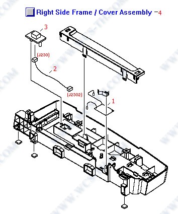
250 Sheet Tray - Right Side Frame / Cover Assembly
| Pic No. | Parts ID | Parts Name | Link |
| 1 | RG5-7617-000CN | Interconnecting feed drive PC board - Mounts in the right side support frame/cover assembly of the 250-sheet input tray assembly | Find 1 |
| 2 | RG5-7433-000CN | Cable assembly - Connects between the Interconnecting feed drive PC board and the printer connector - Mounts in the right side support frame/cover assembly of the 250-sheet input tray assembly | Find 2 |
| 3 | WS1-6337-000CN | Dual connector - Houses both a 8-pin and 6-pin connector - Interconnects the printer with the 250-sheet tray assembly - Mounts in the right side support frame/cover assembly | Find 3 |
| 4 | RG5-7634-000CN | Right side support frame/cover assembly - Includes the frame/cover, printer interface connector, cable, feed drive PC board, and snap-on lid - For the base on the 250-sheet input tray assembly | Find 4 |
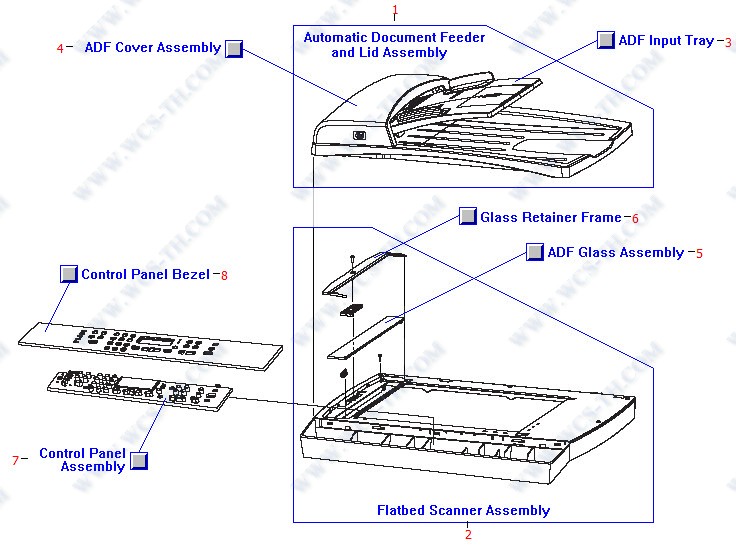
Automatic Document Feeder (ADF) and Scanner Assembly
| Pic No. | Parts ID | Parts Name | Link |
| 1 | Q3948-60189 | Automatic document feeder (ADF) and flatbed scanner lid - Includes the lid, and the ADF feed mechanism - Does not include ADF input tray - Mounts on top of the scanner assembly | Find 1 |
| 1 | Q3948-67903 | ADF pick roller assembly - Includes two rollers in a bracket assembly - Moves the first few top pages of the input stack where the top page is picked off and feed to the pre-scan drive rollers - Mounts in the middle of the ADF assembly | Find 1 |
| 2 | Q3948-60191 | Flatbed scanner assembly - Does NOT include the ADF assembly - Mounts to the top of the printer | Find 2 |
| 3 | Q3948-60214 | Paper input tray for the ADF assembly - Includes the plastic try and width adjustment side rails | Find 3 |
| 4 | Q3948-40007 | ADF cover assembly (ONLY) - Covers the paper pickup and feed mechanism - Mounts on the left end of the ADF and flatbed scanner lid assembly | Find 4 |
| 5 | C7296-00014 | ADF glass window (ONLY) - Small glass window that mounts on the left end of the scanner assembly - Used when scanning documents from the ADF assembly | Find 5 |
| 6 | Q1636-40037 | ADF glass retainer (C-shaped plastic frame) - Holds the ADF glass in place - Mounts on the left end of the flatbed scanner assembly | Find 6 |
| 7 | Q3948-60111 | Control panel assembly - Includes alphanumeric, menu, cancel, scan, and copy buttons and the display - Does NOT include the bezel - Mounts on the front deck of the scanner assembly | Find 7 |
| 7 | Q3949-60134 | Control panel assembly - Includes alphanumeric, menu, cancel, scan, copy, and fax buttons and the display - Does NOT include the bezel - Mounts on the front deck of the scanner assembly | Find 7 |
| 8 | Q3950-60101 | Control panel bezel - Rectangular plastic piece with cutouts for the control function keys and display (English) - Mounts on the front deck of the scanner assembly | Find 8 |
| 8 | Q3950-60124 | Control panel bezel - Rectangular plastic piece with cutouts for the control function keys and display (Thai) - Mounts on the front deck of the scanner assembly | Find 8 |
External Covers
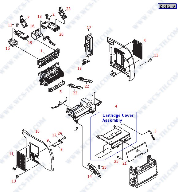
| Pic No. | Parts ID | Parts Name | Link |
| 1 | RB3-1130-000CN | Upper rear cover assembly - Also guides the paper from the fusing assembly to the top output (face down) tray - Mounts on the upper rear of the printer mechanism | Find 1 |
| 2 | Q3948-67909 | Right link mount kit - Includes the|L| shaped plastic piece that has a recess for the printer-to-scanner link and scanner hinge, and the scanner release lift spring - Mounts on the upper rear right side of the print mechanism | Find 2 |
| 2 | RS6-2772-000CN | Torsion spring - Mounts on the right link mount of the printer - Provides upward presure to help lift up the scanner assembly when the scanner is unlatched | Find 2 |
| 3 | RB3-0089-030CN | Top cover rack arm (Black) - Plastic arm with teeth on bottom edge - Disengages the imaging drum/transfer assembly drive cams when the top door is open - Mounts on the lower right side of the cartridge access door | Find 3 |
| 4 | RF5-4055-000CN | Cartridge access door (ONLY) - Provides access to the toner cartridges and imaging drum/transfer assembly cartridge - Does NOT include the upper front cover - Mounts to the top rear cover | Find 4 |
| 5 | RB3-1136-000CN | Face-down paper output cover (|L| shaped plastic) - Serves as the rear of the tray for the face-down output on top of the printer - Mounts under the top rear cover assembly | Find 5 |
| 6 | RB3-1138-000CN | Memory access door - Provides access for changing or adding DIMM memory modules to the printer - Mounts to the right side cover | Find 6 |
| 7 | RG5-7645-000CN | Left scanner link assembly - Spring loaded arm - Connects between the top of the printer and the bottom of the scanner - Allows for limited tilting of the scanner assembly for toner cartridges and image drum/transfer assembly cartridge access | Find 7 |
| 8 | Q3948-67911 | Power switch rod kit - Includes the power switch push rod, compression spring, and mount retainer - Mounts on the inside of the left cover assembly | Find 8 |
| 8 | RS6-2771-000CN | Compression spring - Provides tension for the power switch button - Mounts on the left side cover | Find 8 |
| 9 | Q3948-67911 | Power switch rod kit - Includes the power switch push rod, compression spring, and mount retainer - Mounts on the inside of the left cover assembly | Find 9 |
| 9 | RB3-1145-000CN | Power switch rod - Goes between the power button and the power switch on the low voltage power supply board - Mounts on the left side cover | Find 9 |
| 10 | RB3-1128-000CN | Left side cover (ONLY) - Does NOT include the vent cover or power switch button - Mounts on the left side of the printer | Find 10 |
| 11 | RB3-1139-000CN | Vent cover - Rectangular plastic cover with molded-in ventilation louvers - Mounts on the left side cover | Find 11 |
| 12 | Q3948-67911 | Power switch rod kit - Includes the power switch push rod, compression spring, and mount retainer - Mounts on the inside of the left cover assembly | Find 12 |
| 12 | RB3-1146-000CN | Mount retainer - Holds the spring loaded power switch rod on the left side cover | Find 12 |
| 13 | XA9-1500-000CN | M3 pan-head Phillips screw with flat washer - 8mm long - Used to secure the fusing connector holder to the base pan assembly and the fusing assembly upper cover to the structure | Find 13 |
| 14 | RB3-1126-000CN | Upper left cover - Small cover that is part of the inner side wall in the cartridge access area and provides support for the exterior left side cover | Find 14 |
| 15 | RB3-1131-000CN | Left rear cover - |U| shaped cover that mounts on the under-side of the extension for the left scanner hinge | Find 15 |
| 16 | RB3-1132-000CN | Right rear cover - |U| shaped cover that mounts on the under-side of the extension for the right scanner hinge - Covers the scanner interconnection cables | Find 16 |
| 17 | RB3-1137-000CN | I/O cover - Rectangular plastic cover with a recessed cutout for the interface connectors - Mounts on the right rear of the printer | Find 17 |
| 18 | RB3-1147-000CN | Rear foot - Helps in printer stability when the scanner has been lifted up - Also forms a recess for the alignment peg on the optional paper tray - Mounts on the rear of the printer below the I/O cover | Find 18 |
| 19 | RB3-1154-000CN | Left link mount - Rectangular plastic piece that has a recess for the printer-to-scanner link and includes the bottom half of the scanner hinge - Mounts on the upper rear left side of the print mechanism | Find 19 |
| 20 | Q3948-67909 | Right link mount kit - Includes the|L| shaped plastic piece that has a recess for the printer-to-scanner link and scanner hinge, and the scanner release lift spring - Mounts on the upper rear right side of the print mechanism | Find 20 |
| 20 | RB3-1158-000CN | Right link mount - |L| shaped plastic piece that has a recess for the printer-to-scanner link and includes the bottom half of the scanner hinge - Mounts on the upper rear right side of the print mechanism | Find 20 |
| 21 | RB3-1125-000CN | Upper front cover - Rectangular plastic piece with recess for the printer logo - Mounts to the cartridge access cover assembly | Find 21 |
| 22 | RB3-1083-000CN | Face-down paper exit arm - Helps to prevent paper re-entering the printer and paper curl - Mounts on the right side of the top cover output tray | Find 22 |
| 23 | RG5-7630-000CN | Right scanner link assembly - Spring loaded arm - Connects between the top of the printer and the bottom of the scanner - Allows for limited tilting of the scanner assembly for toner cartridges and image drum/transfer assembly cartridge access | Find 23 |
| 24 | XB4-5300-809CN | M3 pan-head phillips screw with plastite threads - 8mm long - Used to secure the power button mount to the left side cover | Find 24 |
| 25 | XB4-7401-005CN | M4 pan-head phillips screw with self-tapping threads - 10mm long | Find 25 |
External Covers (Assemblies)
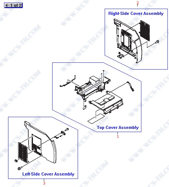
| Pic No. | Parts ID | Parts Name | Link |
| 1 | RG5-7597-000CN | Top cover assembly - Includes the rear cover with molded-in face-down output tray and the lift-up toner cartridge / imaging drum and transfer assembly cartridge access door - Does NOT include the upper front cover - Mounts to the top of the printer | Find 1 |
| 2 | RG5-7599-000CN | Right side cover assembly - Includes the right side cover, DIMM memory access door, and the formatter grounding plate | Find 2 |
| 3 | RG5-7598-000CN | Left side cover assembly - Includes the main cover, vent cover, power switch button, rod and spring (The power switch is located on the low voltage power supply board) | Find 3 |
Front Frame Assembly
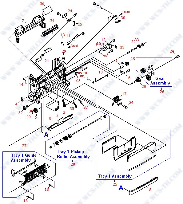
| Pic No. | Parts ID | Parts Name | Link |
| 1 | RB2-9952-000CN | Tray 1 flag spring - Provides torsion for the tray 1 paper sensor flag - Mounts in the lower portion of the front frame assembly | Find 1 |
| 2 | RB9-0890-000CN | Tray hinge - |L| shaped plastic arm - For the right side of the multipurpose front input tray (tray 1) - Mounts in the lower portion of the front frame assembly | Find 2 |
| 3 | RB9-0889-000CN | Tray hinge - |L| shaped plastic arm - For the left side of the multi-purpose front input tray (tray 1) - Mounts in the lower portion of the front frame assembly | Find 3 |
| 4 | RB2-3043-000CN | Left roller bushing - Acts as the bearing and retainer for the left end of the paper pickup roller assembly (tray 1) - Mounts on the left side of the front frame assembly | Find 4 |
| 5 | RB2-3044-000CN | Right roller bushing - Acts as the bearing and retainer for the right end of the paper pickup roller assembly (tray 1) - Mounts on the right side of the front frame assembly | Find 5 |
| 6 | RB2-6248-000CN | Damper assembly (Gray plastic piece with small 13-tooth gear on it) - Helps to reduce clunking when the paper pickup roller is engaged - Engages the paper pickup roller - Mounts on the right side of the front frame assembly | Find 6 |
| 7 | Q3948-67914 | Internal cover kit - Includes the curved plastic cover (with recessed area for grasping the handle on the imaging drum/transfer assembly) and the cartridge removal label - Mounts towards the front of the printer just above multipurpose tray (tray 1) | Find 7 |
| 7 | RB3-1134-000CN | Internal cover (ONLY) - Curved plastic piece with recessed area for grasping the handle on the imaging drum/transfer assembly - Mounts towards the front of the printer just above the multipurpose tray | Find 7 |
| 8 | RB3-1135-000CN | Lower front cover - Rectangular plastic strip - Mounts just below the multipurpose input tray on the front of the printer | Find 8 |
| 9 | RB3-0104-000CN | Roller cover - Covers the multipurpose paper pickup roller assembly - Mounts on the lower front of the front frame assembly | Find 9 |
| 10 | RB3-0111-000CN | Paper flag - Plastic rod with paper sensing flag on one end and sensor activator flag on the other - Senses paper coming from the multi-purpose front input tray (tray 1) | Find 10 |
| 11 | RG5-7624-000CN | Cable assembly (two 3-pin connectors) - Connects between the waste toner sensor PC board (J61) and the DC controller board (J108) | Find 11 |
| 12 | RB3-0120-020CN | Solenoid cover (Steel) - For magnetic wave sheilding - Mounts over the solenoid on the right side of the front frame assembly | Find 12 |
| 13 | RB3-0121-000CN | Right retaining spring - Helps to secure and ground the imaging drum/transfer assembly in the printer - Mounts on the upper right side of the front frame assembly | Find 13 |
| 14 | RB3-0122-000CN | Left retaining spring - Helps to secure the imaging drum/transfer assembly in the printer - Mounts on the upper left side of the front frame assembly | Find 14 |
| 15 | RB3-0135-000CN | Test print flag (Black lever) - Used to activate the print engine test switch - Mounts in a metal holder in the upper left of the front frame assembly | Find 15 |
| 16 | RH7-5383-000CN | Solenoid assembly - (SL92) Lever on the solenoid disengages the stop on the drive gear on the paper pickup roller for the multipurpose input tray (tray 1) - (SL92) Lever on the solenoid disengages the stop on the drive gear on the paper pickup roller for | Find 16 |
| 17 | Q3948-67907 | Paper pickup roller replacement kit - Includes the pickup roller (|D| shaped roller), separation pad, and illustrated instructions - Picks paper from the multipurpose front input tray (tray 1) - Mounts in the lower portion of the frame assembly | Find 17 |
| 17 | RF5-4012-000CN | Separation pad assembly - Includes the separation pad, holder and spring - Mounts below the multipurpose front input (Tray 1) pickup roller assembly | Find 17 |
| 18 | RS6-2030-000CN | Tension spring - Provides support tension for the multipurpose front input tray guide assembly (two used) | Find 18 |
| 19 | RS7-0418-000CN | 26 tooth gear (Black plastic) - Has 1/8th portion of gear cut away - Mounts on the end of the paper pickup roller for the multipurpose input tray (Tray 1) | Find 19 |
| 20 | Q3948-67928 | Front frame gear kit - Includes the 20 tooth/40 tooth dual gear, 26 tooth gear, metal plate with two gears assembly and the bushing for the paper pickup clutch gear shaft - All mount on the right side of the front frame assembly - | Find 20 |
| 20 | RS7-0424-000CN | Dual gear - 20 tooth / 40 tooth - Mounts between the right side of the front frame assembly and the paper pickup gear plate assembly | Find 20 |
| 21 | RS7-0426-000CN | Dual gear - 26 tooth / 50 tooth (White plastic) - Part of the drive gears for the registration roller - Mounts on inside of the front frame assembly on the right side | Find 21 |
| 22 | Q3948-67928 | Front frame gear kit - Includes the 20 tooth/40 tooth dual gear, 26 tooth gear, metal plate with two gears assembly and the bushing for the paper pickup clutch gear shaft - All mount on the right side of the front frame assembly - | Find 22 |
| 22 | RS7-0429-000CN | 26 tooth gear (White plastic) - Has recess for shaft drive pin - Paper pickup clutch drive gear - Mounts between the right side of the front fame assembly and the paper pickup gear plate assembly | Find 22 |
| 23 | WG8-5593-000CN | Sensor PC board - Small board with flag activated photosensor - (PS718) Detects paper from the multipurpose input tray, mounts on the right side of the front frame assembly - (PS720) Front of page sensor for the fusing assembly, mounts on the underside of | Find 23 |
| 24 | XB4-7401-005CN | M4 pan-head phillips screw with self-tapping threads - 10mm long | Find 24 |
| 25 | RG5-7601-000CN | Multipurpose front input tray assembly (tray 1) - Includes the front cover piece, pull-out paper support, and the flip-out extender - Mounts on front of printer (on the front frame assembly) | Find 25 |
| 26 | Q3948-67928 | Front frame gear kit - Includes the 20 tooth/40 tooth dual gear, 26 tooth gear, metal plate with two gears assembly and the bushing for the paper pickup clutch gear shaft - All mount on the right side of the front frame assembly - | Find 26 |
| 26 | RG5-6938-030CN | Gear assembly - Metal plate with two white plastic gears attached | Find 26 |
| 27 | RG5-7584-000CN | Paper guide assembly - Paper width adjustable guide assembly for the multipurpose front input tray (tray 1) - Mounts with the two hinges on the lower portion of the front frame assembly | Find 27 |
| 28 | Q3948-67907 | Paper pickup roller replacement kit - Includes the pickup roller (|D| shaped roller), separation pad, and illustrated instructions - Picks paper from the multipurpose front input tray (tray 1) - Mounts in the lower portion of the frame assembly | Find 28 |
| 28 | Q3948-67912 | Paper pickup roller kit - Includes the |D| shaped the paper pickup roller assembly and the separation pad assembly - For the multipurpose front input tray (tray 1) | Find 28 |
| 28 | RB3-0160-000CN | Paper pickup roller (|D| shaped) - Mounts on the paper pickup roller assembly for the multipurpose front input tray (tray 1) | Find 28 |
| 28 | RG5-6952-020CN | Paper pickup roller assembly - Includes the shaft, guide assembly cams, the D-shaped roller, and roller retainers - Picks paper from the multipurpose front input tray (tray 1) - Mounts in the lower portion of the front frame assembly | Find 28 |
| 29 | WT2-5700-000CN | Cable clamp - White plastic clamp with mounting pin - Mounts on the upper right side of the front frame assembly, the lower left side of the middle frame assembly, and the lower middle of the fusing assembly (three used) | Find 29 |
| 30 | RG5-7131-000CN | E-label reader (contact board only) - Connects the cartridge non-volitale memory to the DC controller board - Mounts to the top left on the front frame assembly | Find 30 |
| 31 | WT2-5056-000CN | Cable clip - |C| shaped White plastic - Mounts in the opening on the cover for the paper pickup solenoid | Find 31 |
| 32 | RS7-0425-000CN | 30 tooth gear (White plastic) - Part of the drive gears for the registration roller - Mounts on inside of the front frame assembly on the right side | Find 32 |
| 33 | Q3948-67928 | Front frame gear kit - Includes the 20 tooth/40 tooth dual gear, 26 tooth gear, metal plate with two gears assembly and the bushing for the paper pickup clutch gear shaft - All mount on the right side of the front frame assembly - | Find 33 |
| 33 | RS5-1635-000CN | Shaft bushing - For the paper pickup clutch gear shaft - Mounts on the plate of the multipurpose paper pickup gear assembly | Find 33 |
| 34 | RF5-4047-000CN | Light blocking pad assembly - Black plastic frame with soft rubber gasket and stiff conductive Mylar piece (grounded) - Mounts to the top center of the front frame assembly | Find 34 |
| 35 | RB2-9954-000CN | Left paper feed guide (small Black plastic arm) - Mounts to the left of the separation pad assembly on the lower front frame assembly | Find 35 |
| 36 | Q3948-67914 | Internal cover kit - Includes the curved plastic cover (with recessed area for grasping the handle on the imaging drum/transfer assembly) and the cartridge removal label - Mounts towards the front of the printer just above multipurpose tray (tray 1) | Find 36 |
| 36 | RS6-8687-000CN | Label - Illustrates the imaging drum/transfer assembly cartridge removal procedure - Mounts on the upper internal cover | Find 36 |
| 37 | RB2-9955-000CN | Right paper feed guide (small Black plastic arm) - Mounts to the right of the separation pad assembly on the lower front frame | Find 37 |
| 38 | RS5-1638-000CN | Bushing - For the registration roller gear drive shaft on the right side of the front frame assembly, and the left side of the feed roller in the 250-sheet paper input tray assembly | Find 38 |
| 39 | XD2-1100-502CN | E-ring clip - Secures the dual gear to the drive shaft which drives the registration roller - Located on the inside of the front frame assembly | Find 39 |
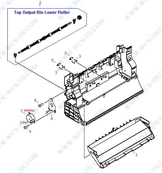
Fusing Assembly
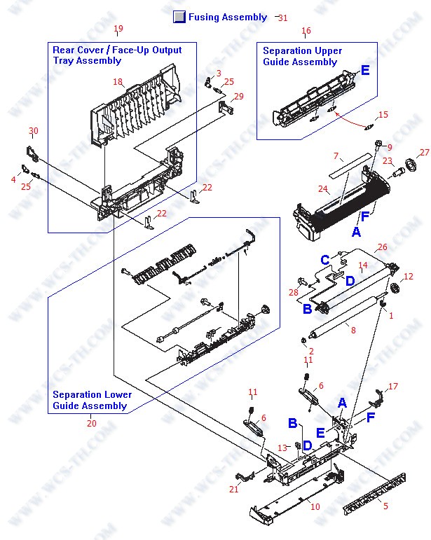
| Pic No. | Parts ID | Parts Name | Link |
| 1 | RB3-1026-000CN | Bushing - Plastic |U| shaped bushing - Mounts on the right end of the pressure roller in the fusing assembly | Find 1 |
| 2 | RB3-1027-000CN | Bushing - Flanged plastic bushing - Mounts on the left end of the pressure roller in the fusing assembly | Find 2 |
| 3 | RB3-0178-000CN | Right side lock release lever - Part of locking system used to secure the fusing assembly in the printer | Find 3 |
| 4 | RB3-0179-000CN | Left side lock release lever - Part of locking system used to secure the fusing assembly in the printer | Find 4 |
| 5 | RB3-0180-000CN | Paper inlet guide - Small ribbed plastic piece - Mounts on the lower front of the fusing assembly | Find 5 |
| 6 | RB3-1024-000CN | Pressure plate - Small steel channel shaped plate - Spring loaded plate that provides upward force on the pressure roller (two used) | Find 6 |
| 7 | RU5-8125-000CN | |Caution: High temperature| label - Mounts in a recess on the upper cover of the fusing assembly | Find 7 |
| 8 | RB3-1034-000CN | Pressure roller assembly - Hard rubber roller on a metal drive shaft - Lower roller in the fusing assembly | Find 8 |
| 9 | XA9-1500-000CN | M3 pan-head Phillips screw with flat washer - 8mm long - Used to secure the fusing connector holder to the base pan assembly and the fusing assembly upper cover to the structure | Find 9 |
| 10 | RF5-4060-000CN | Base plate - Bottom support plate for the fusing assembly | Find 10 |
| 11 | RB3-1025-000CN | Compression spring - Provides upward force on the pressure roller - Mounts between the two guide plates and the fuser support frame assembly (two used) | Find 11 |
| 12 | RS7-0580-000CN | 30 tooth gear - Main drive gear for the fusing assembly - Mounts on the end of the pressure roller drive shaft | Find 12 |
| 13 | WT2-5700-000CN | Cable clamp - White plastic clamp with mounting pin - Mounts on the upper right side of the front frame assembly, the lower left side of the middle frame assembly, and the lower middle of the fusing assembly (three used) | Find 13 |
| 14 | RG5-7162-030CN | Fusing film assembly (for 110VAC to 127VAC operation) - Includes the heater assembly and the fusing film tube | Find 14 |
| 14 | RG5-7163-030CN | Fusing film assembly (for 220VAC to 240VAC operation) - Includes the heater assembly and the fusing film tube | Find 14 |
| 15 | RB2-9950-000CN | Pinch-roller - Small roller mounted on a shaft - Rolls against the paper delivery roller in the fusing assembly - Snaps in molded-in holders on the separation upper guide assembly (two used) | Find 15 |
| 16 | RG5-7576-000CN | Separation upper guide assembly - Ribbed plastic channel with pivot pins on each end and two pinch rollers for the paper delivery roller - Mounts just behind the pressure roller in the fusing assembly | Find 16 |
| 17 | RB3-1166-000CN | Right pressure release lever - To release pressure between the pressure roller and the heater assembly to clear paper jams - Mounts on the right side of the fuser support frame assembly | Find 17 |
| 18 | RB3-1140-010CN | Rear cover / face-up output tray - When opened, routes printed pages to this cover/tray for face-up output - | Find 18 |
| 19 | RG5-7604-010CN | Rear cover/face-up output tray assembly - Includes the tray/cover and the lower fusing assembly cover - When opened, routes printed pages to this cover/tray for face-up output - | Find 19 |
| 20 | RG5-7577-030CN | Lower guide assembly - Includes the support structure, delivery roller, drive gear, paper photo-sensor, sensor flags, and upper separation guide - Mounts on the rear of the fuser support frame assembly | Find 20 |
| 21 | RB3-1167-000CN | Left pressure release lever - To release pressure between the pressure roller and the heater assembly to clear paper jams - Mounts on the left side of the fuser support frame assembly | Find 21 |
| 22 | RB3-1150-000CN | Grounding spring - Mounts between the fusing assembly lower rear cover and fuser support frame assembly (two used) | Find 22 |
| 23 | RB3-1029-000CN | Gear holder - Hollow tube with locking tab - Retains the idler gear on the right side of the fusing assembly | Find 23 |
| 24 | RB3-1032-000CN | Fusing assembly upper cover - Ribbed cover with end caps - Mounts to the top of the fusing assembly | Find 24 |
| 25 | RB2-4933-000CN | Lock release shaft - Small shaft with locking tab - Does NOT include the lock release lever - Used to secure the fusing assembly in the printer (two used) | Find 25 |
| 26 | RG5-7154-000CN | Fusing assembly cable (for 110VAC to 127VAC operation) - Connects the fusing heater assembly and the paper sensor to the fusing assembly connector | Find 26 |
| 26 | RG5-7155-000CN | Fusing assembly cable (for 220VAC to 240VAC operation) - Connects the fusing heater assembly and the paper sensor to the fusing assembly connector | Find 26 |
| 27 | RS7-0582-000CN | 28 tooth idler gear - Mounts to the upper right side of the fusing assembly | Find 27 |
| 28 | XA9-1449-000CN | M3 pan-head Phillips screw with machine threads - 8mm long - Used to secure the thermistor to the right side plate and the power supply PC boards and holders the the base pan assembly and the ground terminal to the fuser support frame | Find 28 |
| 29 | RB2-9934-000CN | Right spacer - Shipping lock for the fusing assembly - Mounts in the lower rear cover of the fusing assembly | Find 29 |
| 30 | RB2-9935-000CN | Left spacer - Shipping lock for the fusing assembly - Mounts in the lower rear cover of the fusing assembly | Find 30 |
| 31 | RG5-7602-070CN | Fusing assembly - Includes the fusing mechanism, lower rear cover (with the two locking levers), and the rear cover/face-up output tray - Bonds the toner to the paper with heat - For 110V to 127VAC operation - | Find 31 |
| 31 | RG5-7603-080CN | Fusing assembly - Includes the fusing mechanism, lower rear cover (with the two locking levers), and the rear cover / face-up output tray - Bonds the toner to the paper with heat - For 220V to 240VAC operation - | Find 31 |
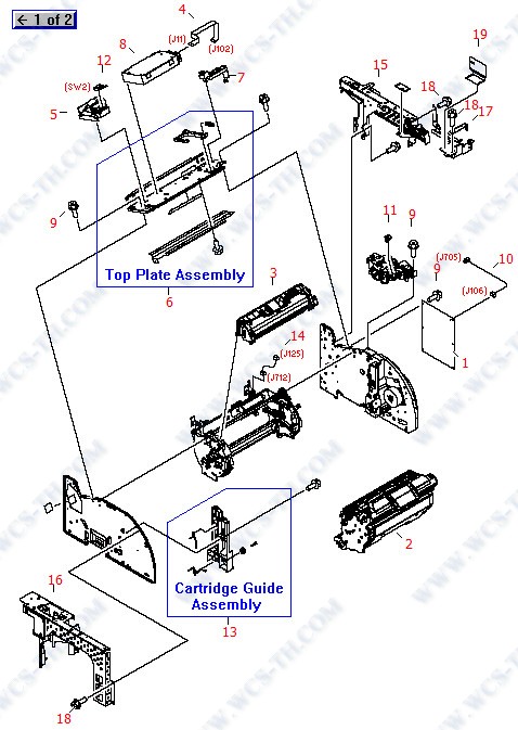
Internal Components (1 of 2)

| Pic No. | Parts ID | Parts Name | Link |
| 1 | RB3-0019-000CN | Toner catch tray (curved Black plastic piece) - Holds residual toner from photosensitive drum - Mounts just below the toner cartridge carousel on the bottom frame assembly | Find 1 |
| 2 | RB2-9932-000CN | RFI shield - Parallel wire form mounted over the fan - Mounts on the fan air duct assembly on the left side of the printer | Find 2 |
| 3 | Q3948-67915 | Airflow guide (duct) kit - Includes the airflow guide / fan holder bracket assembly with high voltage label - Mounts on the left metal side frame assembly | Find 3 |
| 3 | RB9-0901-000CN | Airflow guide (duct) / fan holder bracket assembly (Alloy Gray plastic) - Mounts on the left metal side frame assembly | Find 3 |
| 4 | RB3-0091-000CN | 16 tooth gear (Black plastic) - Gear with large stop tooth and shaft lock tab - Used as part of the mechanism to disengage the drive cams for the imaging drum/transfer assembly - Mounts on the inside of the right side metal chassis assembly | Find 4 |
| 5 | RB3-0092-000CN | 15 tooth gear with drive shaft (Black plastic) - Used as part of the mechanism to disengage the drive cams for the imaging drum/transfer assembly - Mounts on the right side metal chassis frame | Find 5 |
| 6 | XA9-1449-000CN | M3 pan-head Phillips screw with machine threads - 8mm long - Used to secure the thermistor to the right side plate and the power supply PC boards and holders the the base pan assembly and the ground terminal to the fuser support frame | Find 6 |
| 7 | XA9-1495-000CN | Wafer head machine screw - M3, 6mm long, No. 2 Phillips recess - Secures metal to sheet metal - Used internally to secure brackets, plates, the pickup solenoid, and the drive motor to the left and right side plates | Find 7 |
| 8 | RB3-1113-000CN | Grounding plate - Small plate with grounding finger - Grounds the end of the carousel drive shaft - Mounts towards the top on the left side plate assembly | Find 8 |
| 9 | RH7-1630-000CN | Cooling fan (Panaflo Model FBA08T24H - 80mm X 80mm X 15mm high, DC brushless, 24V DC, 190mA) - (FM712) Mounts in the airflow guide/fan bracket assembly on the left side of the printer | Find 9 |
| 10 | RH7-5389-000CN | Electromagnetic clutch assembly (24V) - Electrical clutch between the clutch drive gear and shaft - (CL1) Engages the registration roller assembly | Find 10 |
| 11 | XA9-1501-000CN | M3 pan-head Phillips screw - 10mm long - Used to secure the fusing assembly drive motor to the right side plate (four used) | Find 11 |
| 12 | RH7-7159-000CN | Thermistor - Mounts to the metal right side frame assembly just above the DC controller board | Find 12 |
| 13 | RG5-7160-000CN | Upper cable assembly (seven connectors) - Interconnects various upper level components to the DC controller board | Find 13 |
| 14 | RG5-7145-000CN | Front cable assembly (six connectors) - From various components on the front frame assembly and right side to the DC controller board | Find 14 |
| 15 | RG5-7637-000CN | Upper top bin output roller assembly - Includes the shaft with four rubber rollers, two bushing/shaft retainers, two anti-reversing flaps, and the drive gear - Mounts on the top rear of the printer | Find 15 |
| 16 | RG5-7620-000CN | Cable assembly (two 5-pin connectors) - Connects between the DC controller board (J139) and the fusing assembly drive motor (J702) | Find 16 |
| 17 | RH7-1628-000CN | Fusing motor assembly - 24VDC motor mounted on a motor controller PC board - (DCM702) Mounts on the right side plate assembly (next to the DC controller board) | Find 17 |
| 18 | Q3948-67916 | Paper output gear kit - Includes the 32 tooth / 37 tooth dual gear, the 37 tooth / 43 tooth dual gear, and the 51 tooth gear - Mounts on the right side of the rear frame assembly | Find 18 |
| 18 | RS7-0435-000CN | Dual gear - 32 tooth / 37 tooth (White plastic) - Drives the upper top bin output roller - Mounts on the right side of the rear frame assembly | Find 18 |
| 19 | Q3948-67916 | Paper output gear kit - Includes the 32 tooth / 37 tooth dual gear, the 37 tooth / 43 tooth dual gear, and the 51 tooth gear - Mounts on the right side of the rear frame assembly | Find 19 |
| 19 | RS7-0436-000CN | Dual gear - 37 tooth / 43 tooth (White plastic) - Part of the gear train for driving the upper top bin output roller - Mounts on the right side of the rear frame assembly | Find 19 |
| 20 | Q3948-67916 | Paper output gear kit - Includes the 32 tooth / 37 tooth dual gear, the 37 tooth / 43 tooth dual gear, and the 51 tooth gear - Mounts on the right side of the rear frame assembly | Find 20 |
| 20 | RS7-0437-000CN | 51 tooth gear (White plastic) - Main drive gear for both the upper and lower top bin output rollers | Find 20 |
| 21 | Q3948-67917 | Upper face-down pressure roller kit - Includes the two small Black hard plastic rollers and corresponding torsion springs - Mounts on the top rear of the rear frame assembly | Find 21 |
| 21 | RB2-9905-000CN | Torsion spring - Provides pressure for the upper top bin output pressure rollers (two used) | Find 21 |
| 22 | Q3948-67917 | Upper face-down pressure roller kit - Includes the two small Black hard plastic rollers and corresponding torsion springs - Mounts on the top rear of the rear frame assembly | Find 22 |
| 22 | RF5-4068-000CN | Pressure roller (small Black hard plastic |solid| roller) - Presses against the lower top bin output roller on the middle rear of the printer (two used) | Find 22 |
| 23 | Q3948-67915 | Airflow guide (duct) kit - Includes the airflow guide / fan holder bracket assembly with high voltage label - Mounts on the left metal side frame assembly | Find 23 |
| 23 | RS6-8668-000CN | High voltage caution label - Mounts on the airflow guide / fan bracket assembly | Find 23 |
| 24 | XD2-1100-322CN | E-ring retainer clip - Used to secure the electromagnetic clutch assembly (CL1) on the paper pickup shaft | Find 24 |
| 25 | XB4-7401-005CN | M4 pan-head phillips screw with self-tapping threads - 10mm long | Find 25 |
Internal Components (2 of 2)
| Pic No. | Parts ID | Parts Name | Link |
| 1 | RG5-7612-000CN | Top of page photoelectric sensor PC board - Includes the photoelectric top of page sensor and the print engine test switch - Mounts on the right side of the printer (Behind the formatter board assembly) | Find 1 |
| 2 | Q3964-67901 | Imaging drum/transfer assembly cartridge - Inserts into printer through the top door - Life expectancy is 20,000 pages for black print ONLY, 5,000 pages for color (typical combined life is approximately 8,000 to 10,000 pages) | Find 2 |
| 2 | Q3964A | Imaging drum/transfer assembly cartridge - Inserts into printer through the top door - Life expectancy is 20,000 pages for black print only, 5,000 pages for color (typical combined life is approximately 8,000 to 10,000 pages) | Find 2 |
| 3 | Q3960-67901 | HP Color LaserJet smart Black print cartridge - Will print approximately 5,000 pages based on a 5% print density (not for Europe) | Find 3 |
| 3 | Q3960-67902 | HP Color LaserJet smart Black print cartridge - Will print approximately 5,000 pages based on a 5% print density (Europe) | Find 3 |
| 3 | Q3960A | HP Color LaserJet smart Black print cartridge - Will print approximately 5,000 pages based on a 5% print density | Find 3 |
| 3 | Q3961-67901 | HP Color LaserJet smart Cyan print cartridge - Will print approximately 4,000 pages based on a 5% print density (not for Europe) | Find 3 |
| 3 | Q3961-67902 | HP Color LaserJet smart Cyan print cartridge - Will print approximately 4,000 pages based on a 5% print density (Europe) | Find 3 |
| 3 | Q3961A | HP Color LaserJet smart Cyan print cartridge - Will print approximately 4,000 pages based on a 5% print density | Find 3 |
| 3 | Q3962-67901 | HP Color LaserJet smart Yellow print cartridge - Will print approximately 4,000 pages based on a 5% print density (not for Europe) | Find 3 |
| 3 | Q3962-67902 | HP Color LaserJet smart Yellow print cartridge - Will print approximately 4,000 pages based on a 5% print density (Europe) | Find 3 |
| 3 | Q3962A | HP Color LaserJet smart Yellow print cartridge - Will print approximately 4,000 pages based on a 5% print density | Find 3 |
| 3 | Q3963-67901 | HP Color LaserJet smart Magenta print cartridge - Will print approximately 4,000 pages based on a 5% print density (not for Europe) | Find 3 |
| 3 | Q3963-67902 | HP Color LaserJet smart Magenta print cartridge - Will print approximately 4,000 pages based on a 5% print density (Europe) | Find 3 |
| 3 | Q3963A | HP Color LaserJet smart Magenta print cartridge - Will print approximately 4,000 pages based on a 5% print density | Find 3 |
| 3 | Q3971-67901 | HP Color LaserJet smart Cyan print cartridge - Will print approximately 2,000 pages at based on a 5% print density (not for Europe) | Find 3 |
| 3 | Q3971-67902 | HP Color LaserJet smart Cyan print cartridge - Will print approximately 2,000 pages based on a 5% print density (Europe) | Find 3 |
| 3 | Q3971A | HP Color LaserJet smart Cyan print cartridge - Will print approximately 2,000 pages based on a 5% print density | Find 3 |
| 3 | Q3972-67901 | HP Color LaserJet smart Yellow print cartridge - Will print approximately 2,000 pages based on a 5% print density (not for Europe) | Find 3 |
| 3 | Q3972-67902 | HP Color LaserJet smart Yellow print cartridge - Will print approximately 2,000 pages based on a 5% print density (Europe) | Find 3 |
| 3 | Q3972A | HP Color LaserJet smart Yellow print cartridge - Will print approximately 2,000 pages based on a 5% print density | Find 3 |
| 3 | Q3973-67901 | HP Color LaserJet smart Magenta print cartridge - Will print approximately 2,000 pages based on a 5% print density (not for Europe) | Find 3 |
| 3 | Q3973-67902 | HP Color LaserJet smart Magenta print cartridge - Will print approximately 2,000 pages based on a 5% print density (Europe) | Find 3 |
| 3 | Q3973A | HP Color LaserJet smart Magenta print cartridge - Will print approximately 2,000 pages based on a 5% print density | Find 3 |
| 4 | RH2-5524-000CN | Flat flexible cable (FFC) assembly - Connects between the laser/scanner assembly (J11) the DC controller board (J102) | Find 4 |
| 5 | RB3-0023-000CN | Interlock switch holder (Quartz Gray plastic) - Does NOT include the micro-switch - Mounts on the support shelf for the laser/scanner assembly (just to the left of the laser/scanner assembly) | Find 5 |
| 6 | RG5-6907-030CN | Laser/scanner support assembly (sheet metal plate) - Crossmember between the two side frames - Support for the laser/scanner assembly, the toner cartridge carousel drive motor, and the cover interlock switch assembly | Find 6 |
| 7 | RB2-9903-000CN | Cable guide (Quartz Gray plastic) - Protects and supports the upper cable assembly - Mounts to the right rear on the laser/scanner support assembly | Find 7 |
| 8 | RG5-6890-030CN | Laser/scanner assembly | Find 8 |
| 9 | XA9-1495-000CN | Wafer head machine screw - M3, 6mm long, No. 2 Phillips recess - Secures metal to sheet metal - Used internally to secure brackets, plates, the pickup solenoid, and the drive motor to the left and right side plates | Find 9 |
| 10 | RG5-7114-020CN | Cable assembly (two 4-pin connectors) with shield - Connects between the cartridge drive motor and the DC controller board | Find 10 |
| 11 | RB2-9852-000CN | Rotary release guide - Small plastic clip that allows for manual carousel rotation (with a straightened paper clip) for removing toner cartridges without power - Mounts in the top front of the rotary drive assembly | Find 11 |
| 12 | RH7-6051-000CN | Microswitch with lever activator - (SW2) Senses when the top cover is open - Mounts in a holder on the scanner support assembly | Find 12 |
| 13 | RG5-6935-020CN | Left cartridge guide assembly - | Find 13 |
| 14 | RG5-7117-000CN | Cable assembly (two 3-pin connectors) - Connects between the engaging sensor (J712) on the toner cartridge carousel and the DC controller board (J125) | Find 14 |
| 15 | RG5-7631-000CN | Right support assembly - Metal frame which supports the top mounted scanner and the camera (photo) memory interface board assembly - Also includes the scanner release button/lever - Mounts to the top of the right side frame assembly | Find 15 |
| 16 | RG5-7632-000CN | Left support assembly - Metal frame which supports the top mounted scanner - Mounts to the top of the left side frame assembly | Find 16 |
| 17 | RB2-9976-000CN | Cross-member support - |L| shaped bracket used to help support the camera (photo) memory card interface boards - Mounts on the upper right front of the right side frame assembly | Find 17 |
| 18 | XA9-1495-000CN | Wafer head machine screw - M3, 6mm long, No. 2 Phillips recess - Secures metal to sheet metal - Used internally to secure brackets, plates, the pickup solenoid, and the drive motor to the left and right side plates | Find 18 |
| 19 | RB3-1379-000CN | Insulator sheet - |L| shaped plastic insulator sheet - Protects the camera (photo) memory interface assembly from shorting against the support bracket - Mounts on the front support bracket on the right support assembly | Find 19 |
Main Drive Assembly
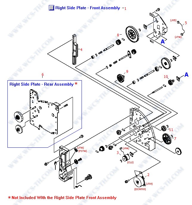
| Pic No. | Parts ID | Parts Name | Link |
| 1 | RG5-7579-070CN | Main drive (right side plate) assembly - Includes the right side plate front assembly (with main motor, clutch, and gears) and the right side plate rear assembly (with drive gears) | Find 1 |
| 1 | RG5-7581-060CN | Right side plate front assembly - Includes the front half of the metal frame assembly, gears, imaging drum/transfer assembly drive cams, cover engaging mechanism, roller engaging clutch (CL2), and main drive motor (DCM701) - Mounts on the right side | Find 1 |
| 2 | RF5-4063-030CN | Main motor assembly - Large motor mounted on a controller PC board - (DCM701) Mounts on the inside of the metal right side frame assembly | Find 2 |
| 3 | RH7-5335-000CN | Electromagnetic clutch assembly (24VDC) - Electrical clutch between the clutch drive gear and shaft - (CL2) Engages the roller within the imaging drum/transfer assembly from the main gear train | Find 3 |
| 4 | RB3-0090-000CN | Rack slide - White plastic piece with gear teeth layed out in rack form on both sides - Part of the mechanism that disengages the imaging drum/transfer assembly cams when the top cover is opened - Mounts vertically on the metal right side frame | Find 4 |
| 5 | RG5-7115-000CN | Cable assembly (two 3-pin connectors) - Connects between the roller engaging photosensor (J714) and the DC controller board (J115) | Find 5 |
| 6 | RG5-7580-020CN | Right side plate rear assembly - Includes the rear half of the metal right side plate and the two associated gears | Find 6 |
| 7 | RS7-0574-000CN | Dual gear - 32 tooth / 123 tooth - Large gear which mounts toward the front on the right side plate front assembly | Find 7 |
| 8 | RS7-0573-000CN | 186 tooth gear - Uppermost large gear that mounts on a short shaft between the gear retainer bracket and the right side plate front assembly | Find 8 |
| 9 | RS7-0572-000CN | Dual gear - 31 tooth / 90 tooth - Mounts on a pin on the right side plate front assembly (between the gear retaining bracket and the right side plate) | Find 9 |
| 10 | RS7-0571-000CN | Dual gear - 23 tooth / 54 tooth - Small gear that mounts toward the front on a short shaft between the gear retainer bracket and the right side plate front assembly | Find 10 |
| 11 | RS7-0570-000CN | 81 tooth gear - Mounts on a pin on the right side plate front assembly (between the gear retaining bracket and the right side plate) | Find 11 |
Major Assembly Locator
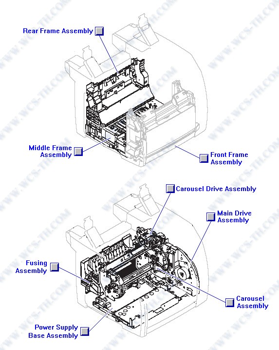
| Pic No. | Parts ID | Parts Name | Link |
Middle Frame Assembly

| Pic No. | Parts ID | Parts Name | Link |
| 1 | Q3948-67918 | Feed belt kit - Includes one paper feed guide drive (large) belt, two 3-belt pulley rollers, two 1-belt pulley rollers, and eight paper feed (small) belts - Mounts just behind the transfer roller in the middle frame assembly | Find 1 |
| 1 | RB1-8668-030CN | Feed guide drive belt - Small belt approximately 5/16 inch wide with |A| shaped ribs on it - Between the feed drive roller and the small center roller - Driven via the transfer roller gear train | Find 1 |
| 2 | Q3948-67918 | Feed belt kit - Includes one paper feed guide drive (large) belt, two 3-belt pulley rollers, two 1-belt pulley rollers, and eight paper feed (small) belts - Mounts just behind the transfer roller in the middle frame assembly | Find 2 |
| 2 | RB3-0061-000CN | Pulley roller (accommodates three feed belts) - Small black roller approximately 3.49cm (1-3/4 inches) long with three ball type pulleys - Mounts just behind the transfer roller in the middle frame assembly (two used) | Find 2 |
| 3 | Q3948-67918 | Feed belt kit - Includes one paper feed guide drive (large) belt, two 3-belt pulley rollers, two 1-belt pulley rollers, and eight paper feed (small) belts - Mounts just behind the transfer roller in the middle frame assembly | Find 3 |
| 3 | RB3-0063-000CN | Paper feed belt - Small black rubber belt approximately 1/8 inch wide with little |A| shaped ribs on it - Goes between the feed drive roller and the pulley rollers (eight used) | Find 3 |
| 4 | RB2-6297-000CN | Rubber foot - Square self-adhesive rubber foot - Attaches to the rear of the middle frame assembly (two used) | Find 4 |
| 5 | RB3-0286-000CN | Contact plate - Runs between the shaft on the registration roller and the metal entrance guide assembly | Find 5 |
| 6 | RB3-0009-000CN | Static eliminator ground plate - Right angled metal piece with small teeth on top edge - Mounts from underneath on the middle frame assembly just behind the pulley rollers | Find 6 |
| 7 | RB3-0010-030CN | Feed plate - Center metal plate with slots that the ribs on the middle frame assembly go through - | Find 7 |
| 8 | Q3948-67919 | Feed shaft kit - Includes the feed drive shaft, the belt roller, the idler gear shaft, and the 23 tooth idler gear - Mounts just behind the transfer roller in the middle frame assembly | Find 8 |
| 8 | RB3-0011-000CN | Feed drive shaft - Long shaft with eight feed belt ball type pulleys and one ribbed feed guide drive belt pulley - Mounts behind the transfer roller on the middle frame assembly | Find 8 |
| 9 | Q3948-67919 | Feed shaft kit - Includes the feed drive shaft, the belt roller, the idler gear shaft, and the 23 tooth idler gear - Mounts just behind the transfer roller in the middle frame assembly | Find 9 |
| 9 | RB3-0012-000CN | Belt roller - Small oval shaped roller approximately 1-3/4 inches long - Mounts toward the center of the metal feed plate on the middle frame assembly | Find 9 |
| 10 | Q3948-67919 | Feed shaft kit - Includes the feed drive shaft, the belt roller, the idler gear shaft, and the 23 tooth idler gear - Mounts just behind the transfer roller in the middle frame assembly | Find 10 |
| 10 | RB3-0060-020CN | Idler gear shaft - Short metal rod - Shaft for the transfer and feed drive idler roller - Mounts on the left side of the middle frame assembly | Find 10 |
| 11 | RB3-0045-000CN | Electrical contact spring - Rear electrical contact spring - Provides high voltage to the toner cartridge via a cable assembly and connection through the carousel plate assembly - Connects to the high voltage board | Find 11 |
| 12 | RB3-0016-000CN | Electrical contact spring - Spring steel wire with compression springs formed on both ends - One end provides upward pressure on the right bushing for the transfer roller - Connects to high voltage board | Find 12 |
| 13 | Q3948-67919 | Feed shaft kit - Includes the feed drive shaft, the belt roller, the idler gear shaft, and the 23 tooth idler gear - Mounts just behind the transfer roller in the middle frame assembly | Find 13 |
| 13 | RB3-0022-000CN | 22 tooth gear (Black plastic) - Small gear with diagonally cut teeth - Idler gear between the transfer roller assembly and the feed drive shaft - Mounts on the left side of the middle frame assembly | Find 13 |
| 14 | RB3-0042-000CN | Electrical contact spring - Mounts on the middle frame assembly behind the transfer roller - Of the four similar springs, this one is next to the one on the far left - Connects to high voltage board | Find 14 |
| 15 | RB3-0043-000CN | Electrical contact spring - Mounts on the middle frame assembly behind the transfer roller - Of the four similar springs, this one is on the far right - Connects to high voltage board | Find 15 |
| 16 | RB3-0044-000CN | Electrical contact spring - (Front) Provides high voltage to the toner cartridge via a cable assembly and connection through the carousel plate assembly - Connects to the high voltage board | Find 16 |
| 17 | RB3-0046-000CN | Electrical contact spring - Mounts on the middle frame assembly behind the transfer roller - Of the four similar springs, this one is just to the left of the one on the far right - Connects to high voltage board | Find 17 |
| 18 | RB3-0047-000CN | Electrical contact spring - Mounts on the underside of the middle frame assembly - Connects to high voltage board | Find 18 |
| 19 | RB3-0048-000CN | Electrical contact spring - Mounts on the middle frame assembly behind the transfer roller - Of the four similar springs, this one is on the far left - Connects to the high voltage board | Find 19 |
| 20 | RS5-1637-000CN | Bushing (black plastic) - Mounts on the right end of the registration roller assembly | Find 20 |
| 21 | RB3-1110-000CN | Insulating sheet (Transparent plastic) - For the power supply base assembly - Mounts to the underside of the middle frame assembly | Find 21 |
| 22 | Q3948-67920 | Transfer roller kit - Includes the transfer roller, two transfer side plates (|U| shaped metal inserts), the right end shaft bushing, and the two compression springs at the left end of the roller - Mounts towards the front and on top of the middle frame | Find 22 |
| 22 | RB3-0057-000CN | Transfer slide plate - Small |U| shaped metal insert plates - Mount in the bushing wells for the transfer roller on the middle frame assembly (two used) | Find 22 |
| 23 | WS1-6336-000CN | Connector assembly - For optional paper tray - Mounts to the bottom right side of the middle frame assembly | Find 23 |
| 24 | RS7-0428-000CN | 30 tooth gear (White plastic) - Mounts on the end of the registration roller drive shaft | Find 24 |
| 25 | RF5-4065-000CN | Entrance guide assembly - Mounts in front of the tranfer roller assembly (behind the transfer inlet guide) | Find 25 |
| 26 | RG5-6939-020CN | Registration roller assembly - Includes the roller, bushings, mounting plate, paper sensor, and the sensor flag - Mounts from the bottom toward the front center of the middle frame assembly | Find 26 |
| 27 | RG5-7123-000CN | Grounding cable assembly - Connects from the optional tray connector housing to the metal right side frame assembly | Find 27 |
| 28 | RG5-6940-050CN | Registration shutter assembly - Includes the metal roller, mounting frame, grounding springs, and the dual coupling gear - Mounts over the registration roller at the front of the middle frame assembly | Find 28 |
| 29 | RG5-7122-000CN | Cable assembly - |Y| type cable (three connectors) - The 14-pin connector splits into an 8-pin connector and a 6-pin connector - Connects between the DC controller board (J118) and the optional paper tray connectors (J230) | Find 29 |
| 30 | RB3-0052-000CN | Gear Cover (Small Black plastic cover) - Covers the left end of the feed drive shaft - Mounts towards the left side of the middle frame assembly | Find 30 |
| 31 | RB3-0065-000CN | Contact plate - copper clad metal spring - Holds the left end of the small 500 Meg-ohm resistor - Mounts on the left side of the middle frame below the entrance guide assembly | Find 31 |
| 32 | RB3-0066-000CN | Contact plate - copper clad metal spring - Holds the right end of the small 500 Meg-ohm resistor - Mounts on the left side of the middle frame below the entrance guide assembly | Find 32 |
| 33 | RB2-9925-000CN | Sensor arm and flag - Activates the photosensor (Does NOT include the roller) - For the Leading edge paper sensor for the fusing assembly (PS720) - Protrudes up through the feed plate on the middle frame assembly | Find 33 |
| 34 | RB2-9924-000CN | Sensor assembly mounting holder - Holds the leading edge paper sensor (PS720) for the fusing assembly - Mounts on the underside left on the middle frame assembly | Find 34 |
| 35 | RB2-7195-000CN | Sensor flag roller (small White plastic roller) - Mounts in the sensor arm flag for the leading edge paper sensor for the fusing assembly (PS720) | Find 35 |
| 36 | Q3948-67918 | Feed belt kit - Includes one paper feed guide drive (large) belt, two 3-belt pulley rollers, two 1-belt pulley rollers, and eight paper feed (small) belts - Mounts just behind the transfer roller in the middle frame assembly | Find 36 |
| 36 | RB3-0067-000CN | Pulley roller (accommodates one feed belt) - Small black roller approximately 1.59cm (5/8 inch) long with one ball type pulley - Mounts just behind the transfer roller in the middle frame assembly (two used) | Find 36 |
| 37 | RG5-7128-000CN | Cable assembly (four 3-pin connectors) - Connects between the DC controller board (J107 and J138) and the leading edge paper sensor for the fusing assembly (J720) and the registration sensor (J711) | Find 37 |
| 38 | WG8-5593-000CN | Sensor PC board - Small board with flag activated photosensor - (PS718) Detects paper from the multipurpose input tray, mounts on the right side of the front frame assembly - (PS720) Front of page sensor for the fusing assembly, mounts on the underside of | Find 38 |
| 39 | RS6-2766-000CN | Tension spring - Provides a small amount of return tension for the sensor flag arm on the leading edge sensor for the fusing assembly (PS720) | Find 39 |
| 40 | RB2-9850-020CN | Terminal contact plate - Provides for a connection between the high voltage cable assembly and the front toner cartridge contact spring - Mounts on the underside left of the middle frame assembly | Find 40 |
| 41 | RB2-9851-020CN | Terminal contact plate - Provides for a connection between the high voltage cable assembly and the rear toner cartridge contact spring - Mounts on the underside left of the middle frame assembly | Find 41 |
| 42 | WT2-5737-000CN | Drawer connector - Connector located on bottom of tray assembly frame on right side, which connects tray assemblies to each other - Mounts on the base pan assembly (two used) | Find 42 |
| 43 | RG5-7130-000CN | High voltage cable assembly - Connects between the high voltage board spring contacts (on the middle frame assembly) and the cables for the toner cartridge carousel left plate assembly (J511 and J512) | Find 43 |
| 44 | WT2-5700-000CN | Cable clamp - White plastic clamp with mounting pin - Mounts on the upper right side of the front frame assembly, the lower left side of the middle frame assembly, and the lower middle of the fusing assembly (three used) | Find 44 |
| 45 | Q3948-67919 | Feed shaft kit - Includes the feed drive shaft, the belt roller, the idler gear shaft, and the 23 tooth idler gear - Mounts just behind the transfer roller in the middle frame assembly | Find 45 |
| 45 | RB2-9999-000CN | Torsion spring - Secures the belt roller (for the feed drive shaft) in the top of the middle frame assembly | Find 45 |
| 46 | Q3948-67920 | Transfer roller kit - Includes the transfer roller, two transfer side plates (|U| shaped metal inserts), the right end shaft bushing, and the two compression springs at the left end of the roller - Mounts towards the front and on top of the middle frame | Find 46 |
| 46 | RF5-4067-030CN | Transfer roller assembly - Long black foam type roller - Transfers static charge to paper - Mounts towards the front and on top of the middle frame assembly | Find 46 |
| 47 | Q3948-67920 | Transfer roller kit - Includes the transfer roller, two transfer side plates (|U| shaped metal inserts), the right end shaft bushing, and the two compression springs at the left end of the roller - Mounts towards the front and on top of the middle frame | Find 47 |
| 47 | RB3-1094-000CN | Bushing assembly (Black plastic bushing with small guide roller on top) - Holds the right end of the transfer roller assembly in the middle frame assmebly | Find 47 |
| 48 | Q3948-67920 | Transfer roller kit - Includes the transfer roller, two transfer side plates (|U| shaped metal inserts), the right end shaft bushing, and the two compression springs at the left end of the roller - Mounts towards the front and on top of the middle frame | Find 48 |
| 48 | RB3-0015-000CN | Compression spring - Provides upward pressure for the left transfer roller bushing | Find 48 |
| 49 | RH5-3169-000CN | Resistor - 500 Meg ohm, 300mW - Mounts on the left side of the middle frame below the entrance guide assembly - Held in place with two small contact plates | Find 49 |
| 50 | RB3-1088-000CN | Transfer inlet guide assembly - Angled metal guide between the registration roller and the transfer roller - Mounts to the middle frame assembly | Find 50 |
| 51 | XB4-7401-005CN | M4 pan-head phillips screw with self-tapping threads - 10mm long | Find 51 |
| 52 | XB2-4300-605CN | M3 pan-head phillips screw with flat washer - 6mm long - Secures the terminals from the high voltage cable assembly to the contact plates on the left side of the middle frame assembly (two used) | Find 52 |
PC Board Assembly Locator
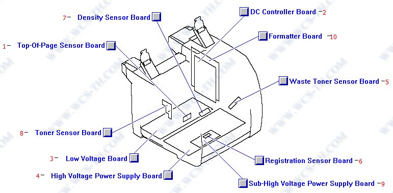
| Pic No. | Parts ID | Parts Name | Link |
| 1 | RG5-7612-000CN | Top of page photoelectric sensor PC board - Includes the photoelectric top of page sensor and the print engine test switch - Mounts on the right side of the printer (Behind the formatter board assembly) | Find 1 |
| 2 | RG5-7646-030CN | DC controller board - Mounts on the right side of the printer (Behind the formatter board assembly) - | Find 2 |
| 3 | RH3-2260-000CN | Low voltage power supply - For 110VAC to 127VAC operation - Includes the AC power input connector and power switch - Mounts in the bottom pan assembly towards the rear of the printer | Find 3 |
| 3 | RH3-2261-000CN | Low voltage power supply - For 220VAC to 240VAC operation - Includes the AC power input connector and power switch - Mounts in the bottom pan assembly towards the rear of the printer | Find 3 |
| 4 | RG5-7647-000CN | High voltage power supply board (HVT) assembly - Has contacts for the eight high voltage springs in the printer - Mounts in the bottom pan assembly (Towards the front of the printer) | Find 4 |
| 5 | RG5-7648-000CN | Waste toner sensor assembly PC board - Detects excess level of waste toner in the imaging drum/transfer assembly cartridge - Mounts on the right side of the front frame assembly | Find 5 |
| 6 | RG5-7613-000CN | Registration sensor PC Board - Small board with flag activated photosensor - (PS711) Mounts in the registration assembly on the underside of the middle frame | Find 6 |
| 7 | RH7-7158-000CN | Density photoelectric sensor PC board - (PS81) Mounts under the light blocking pad on the top of the front frame assembly | Find 7 |
| 8 | RG5-7609-000CN | Carousel position and toner level photoelectric sensor PC board - |L| Shaped PC board with the two sensors - (PS51) Mounts on the left plate in the toner cartridge carousel assembly | Find 8 |
| 9 | RG5-7616-000CN | Sub-high voltage board - Small auxillary PC board - Mounts in a holder just above the high voltage board in the bottom pan assembly | Find 9 |
| 10 | Q3948-69001 | Formatter assembly - Includes the formatter PC board, the metal card cage cover, and cover plate - Mounts on the right side of the print mechanism | Find 10 |
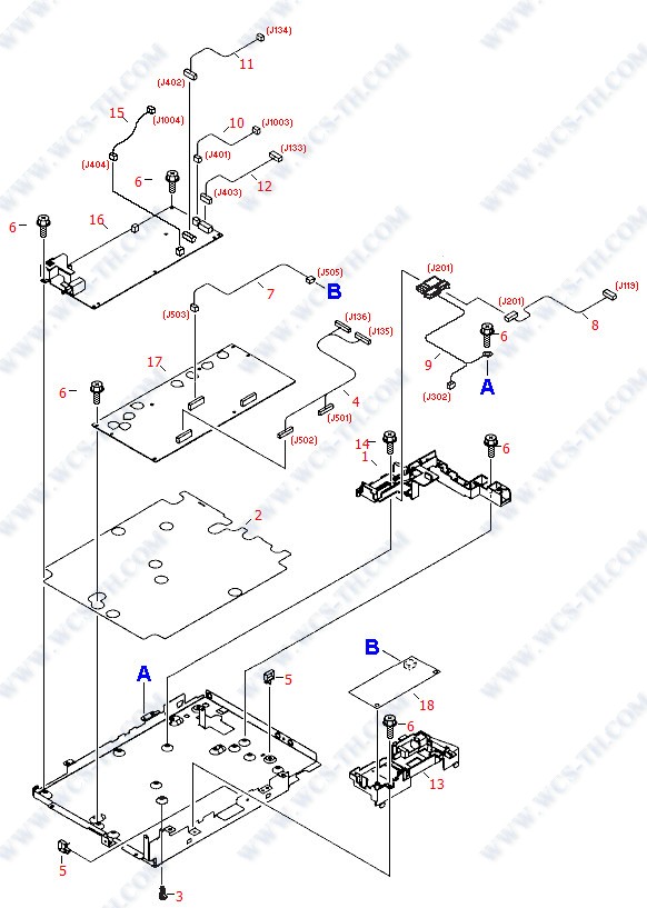
Power Supply Base Assembly
| Pic No. | Parts ID | Parts Name | Link |
| 1 | RB3-0006-000CN | Holder - Housing for the fusing connector assembly - Mounts on the lower base pan of the printer mechanism | Find 1 |
| 2 | RB3-0007-000CN | Insulating sheet (Transparent plastic) - Mounts between the bottom pan and the high and low voltage power supply boards | Find 2 |
| 3 | VT2-0012-005CN | PC Board support - Plastic standoff for supporting a PC board - Supports the high voltage board on the base assembly metal pan (six used) | Find 3 |
| 4 | RG5-7146-000CN | High voltage cable assembly (two 15-pin connectors and two 14-pin connectors) - Connects between the high voltage power supply board (J501 and J502) and the DC controller board (J136 and J135) | Find 4 |
| 5 | WT2-5737-000CN | Drawer connector - Connector located on bottom of tray assembly frame on right side, which connects tray assemblies to each other - Mounts on the base pan assembly (two used) | Find 5 |
| 6 | XA9-1449-000CN | M3 pan-head Phillips screw with machine threads - 8mm long - Used to secure the thermistor to the right side plate and the power supply PC boards and holders the the base pan assembly and the ground terminal to the fuser support frame | Find 6 |
| 7 | RG5-7126-000CN | Cable assembly (two 5-pin connectors) - Connects between the sub-high voltage board (J505) and the high voltage board (J503) | Find 7 |
| 8 | RG5-7109-000CN | Cable assembly (two 7-pin connectors) - Connects between the DC controller board (J119) and the fusing assembly connector (J201) | Find 8 |
| 9 | RG5-7161-000CN | Cable assembly (two 3-pin connectors and a spad lug) - Connects between the fusing assembly connector and the low voltage power supply board (J302), and the chassis ground | Find 9 |
| 10 | RG5-7106-000CN | Cable assembly (two 2-pin connectors) - Connects between the low voltage power supply board (J401) and the formatter board (J1003) | Find 10 |
| 11 | RG5-7621-000CN | Cable assembly (two 8-pin connectors) - Connects between the low voltage power supply board (J402) and the DC controller board (J134) | Find 11 |
| 12 | RG5-7108-000CN | Cable assembly (two 8-pin connectors, Purple wire) - Connects between the low voltage power supply board (J403) and the DC controller board (J133) | Find 12 |
| 13 | RB3-0062-000CN | PC board support (Black plastic holder) - For mounting the small sub-high voltage board above the high voltage board | Find 13 |
| 14 | XA9-1500-000CN | M3 pan-head Phillips screw with flat washer - 8mm long - Used to secure the fusing connector holder to the base pan assembly and the fusing assembly upper cover to the structure | Find 14 |
| 15 | RG5-7156-000CN | Cable assembly (two 2-pin connectors) - Connects between the low voltage power supply board (J404) and the formatter board (J1004) | Find 15 |
| 16 | RH3-2260-000CN | Low voltage power supply - For 110VAC to 127VAC operation - Includes the AC power input connector and power switch - Mounts in the bottom pan assembly towards the rear of the printer | Find 16 |
| 16 | RH3-2261-000CN | Low voltage power supply - For 220VAC to 240VAC operation - Includes the AC power input connector and power switch - Mounts in the bottom pan assembly towards the rear of the printer | Find 16 |
| 17 | RG5-7647-000CN | High voltage power supply board (HVT) assembly - Has contacts for the eight high voltage springs in the printer - Mounts in the bottom pan assembly (Towards the front of the printer) | Find 17 |
| 18 | RG5-7616-000CN | Sub-high voltage board - Small auxillary PC board - Mounts in a holder just above the high voltage board in the bottom pan assembly | Find 18 |
Rear Frame Assembly
| Pic No. | Parts ID | Parts Name | Link |
| 1 | RB2-9904-000CN | Airflow Guide (duct) - Black plastic insert piece which runs the width of the printer and has an air flow hole on right side - Directs air flow from the fan on the left side of the printer to the fusing assembly - Snap locks in center rear of printer | Find 1 |
| 2 | RG5-7595-000CN | Lower top bin output roller assembly - Includes the shaft with four rubber rollers, two bushing/shaft retainers, and the drive gear - Mounts in the center on the rear frame assembly (above the fusing assembly) | Find 2 |
| 3 | Q3948-67922 | Lower face-down pressure roller kit - Includes the two small Black hard plastic rollers and corresponding torsion springs - Mounts on the back-side of the rear frame assembly | Find 3 |
| 3 | RB3-1065-000CN | Torsion spring - Provides pressure for the lower top bin output pressure rollers (two used) | Find 3 |
| 4 | XA9-1495-000CN | Wafer head machine screw - M3, 6mm long, No. 2 Phillips recess - Secures metal to sheet metal - Used internally to secure brackets, plates, the pickup solenoid, and the drive motor to the left and right side plates | Find 4 |
| 5 | Q3948-67922 | Lower face-down pressure roller kit - Includes the two small Black hard plastic rollers and corresponding torsion springs - Mounts on the back-side of the rear frame assembly | Find 5 |
| 5 | RB2-9909-000CN | Pressure roller (small Black hard plastic |solid| roller) - Presses against the lower top bin output roller on the middle rear of the printer (two used) | Find 5 |
| 6 | RB2-9916-020CN | Cover - For the engaging motor (PM704) - Mounts on the upper left side of the rear frame assembly | Find 6 |
| 7 | RH7-1629-000CN | Stepping motor - 24VDC - (PM704) swings (or engages) the toner cartridge carousel in place to transfer toner - Mounts on the left side of the rear frame assembly | Find 7 |
| 8 | XB4-7401-005CN | M4 pan-head phillips screw with self-tapping threads - 10mm long | Find 8 |
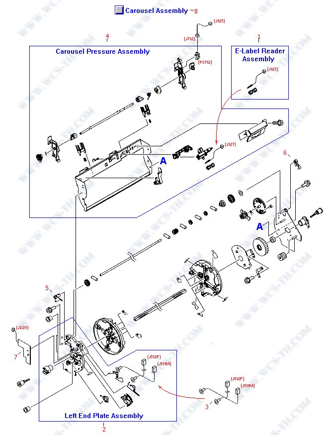
Toner Cartridge Carousel Assembly
| Pic No. | Parts ID | Parts Name | Link |
| 1 | RG5-7132-000CN | E-label reader assembly - Connects cartridge non-volatile memory to the DC controller board - One for the imaging drum/transfer assembly, the other for toner cartridges - One mounts to the front frame assembly, the other to the toner cartridge carousel as | Find 1 |
| 2 | RG5-6942-030CN | Left side carousel plate assembly - End plate under the rotational toner cartridge carousel - Includes all of the high voltage contacts for the toner cartridges - Mounts on the metal carousel support frame | Find 2 |
| 3 | RG5-7129-000CN | Cable assembly (two connectors and two spade lugs) - From toner cartridge contacts on the left carousel side plate to the cable (J512 and J511) that runs to the high voltage power supply board | Find 3 |
| 4 | RG5-7589-000CN | Carousel pressure (support) assembly - Includes the main rear support, E-label reader assembly, engaging sensor, and the engaging rod shaft - Primary support structure for the toner cartridge carousel | Find 4 |
| 5 | RB2-9809-000CN | Bushing/shaft retainer assembly (White plastic) - Holds the rotation drive shaft in the left side plate of the toner cartridge carousel (rotary) assembly | Find 5 |
| 6 | RB9-0879-000CN | Bushing/shaft retainer assembly (Black plastic) - Holds the rotation drive shaft in the right side plate of the toner cartridge carousel (rotary) assembly | Find 6 |
| 7 | RG5-7609-000CN | Carousel position and toner level photoelectric sensor PC board - |L| Shaped PC board with the two sensors - (PS51) Mounts on the left plate in the toner cartridge carousel assembly | Find 7 |
| 8 | RG5-7587-090CN | Carousel (rotary) assembly - Includes the carousel assembly, the support assembly, end plates, drive gears and shaft, sensors, and cables | Find 8 |
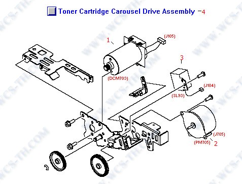
Toner Cartridge Carousel Rotary Drive Assembly
| Pic No. | Parts ID | Parts Name | Link |
| 1 | RH7-1651-000CN | Rotary motor assembly - (DCM703) Rotates the four color toner cartridges in the carousel to position one of them for printing - Mounts in the rotary drive assembly | Find 1 |
| 2 | RH7-1625-000CN | Stepping motor - 24VDC - (PM705) used to drive the internal rollers and mechanisms in the toner cartridge when it has been rotated in the printing position on the carousel - Mounts in the rotary drive assembly | Find 2 |
| 3 | RH7-5384-000CN | Solenoid assembly - (SL93) Engages to stop rotation when the proper toner cartridge on the carousel is in place for printing | Find 3 |
| 4 | RG5-7842-000CN | Rotary drive assembly - Includes the carousel rotating motor (DCM703), toner cartridge drive motor (PM705), developing rotary stopper solenoid (SL93), bracket, and gears - Mounts on the right top rear of the print engine | Find 4 |