คุณยังไม่มีสินค้าในรถเข็น

250-Sheet Tray Assembly (Tray 2)
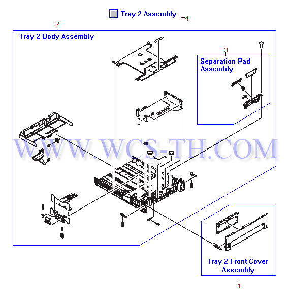
| Pic No. | Parts ID | Parts Name | Link |
| 1 | RM1-1323-030CN | Tray front cover assembly - Mounts to the front of tray 2 | Find 1 |
| 2 | RM1-1294-000CN | 250-sheet (tray 2) body assembly - Includes everything except for the tray front cover assembly | Find 2 |
| 3 | RM1-1298-000CN | Tray 2 separation pad assembly - Includes the pad on a spring loaded arm in a holder frame - Mounts toward the front of the tray | Find 3 |
| 4 | RM1-1322-080CN | 250-sheet input paper tray (tray 2) assembly - Includes the tray body and front cover assemblies | Find 4 |
Engine Control Unit PC Board Assembly
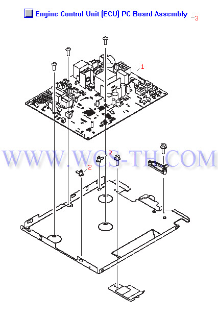
| Pic No. | Parts ID | Parts Name | Link |
| 1 | RM1-1242-030CN | Engine control unit (ECU) PC board - Control and power supply board for the printer (For 110V to 127V operation) - Does NOT includes the power cord connector or power switch - Mounts in the bottom of the printer | Find 1 |
| 1 | RM1-1243-030CN | Engine controlunit (ECU) PC board - Control and power supply board for the printer (For 220V to 240V operation) - Does NOT includes the power cord connector or power switch - Mounts in the bottom of the printer | Find 1 |
| 2 | RA0-1128-000CN | Printed circuit board spacer - Mounts between the engine control PC board and the metal support pan (two used) | Find 2 |
| 3 | RM1-1327-030CN | Engine control unit (ECU) PC board assembly - Includes the PC board, bottom pan, standoffs, and gear cover (For 110V to 127V operation) - Does NOT includes the power cord connector or power switch - Mounts in the bottom of the printer | Find 3 |
| 3 | RM1-1463-030CN | Engine control unit (ECU) PC board assembly - Includes the PC board, bottom pan, standoffs, and gear cover (For 220V to 240V operation) - Does NOT includes the power cord connector or power switch - Mounts in the bottom of the printer | Find 3 |
External Covers
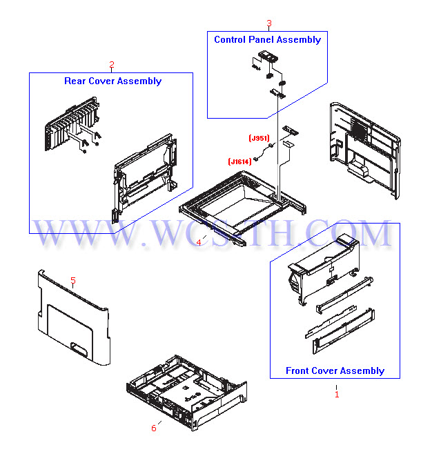
| Pic No. | Parts ID | Parts Name | Link |
| 1 | RM1-1324-080CN | Front cover set - Includes the toner cartridge access door, single sheet priority input slot door, front cover (between tray 2 and the priority input slot), and the noise absorber | Find 1 |
| 2 | RM1-1325-000CN | Rear cover assembly - Includes the rear cover bezel and fold down face-up (or straight through) paper output tray (Tray is NOT sold separately) | Find 2 |
| 3 | RM1-1311-000CN | Control panel assembly - Includes the control panel bezel, 'Go' and 'Cancel' buttons, LED light pipe, and sheild plate (PC board NOT included) - Mounts on the right side of the top cover | Find 3 |
| 4 | RC1-3801-000CN | Top cover assembly - Has face-down paper output tray molded into it | Find 4 |
| 5 | RC1-3812-000CN | Left side printer cover - Has moled-in bezel for the interface port connectors (On the formatter board) | Find 5 |
| 6 | RM1-1322-080CN | 250-sheet input paper tray (tray 2) assembly - Includes the tray body and front cover assemblies | Find 6 |
Internal Components (1 of 4)
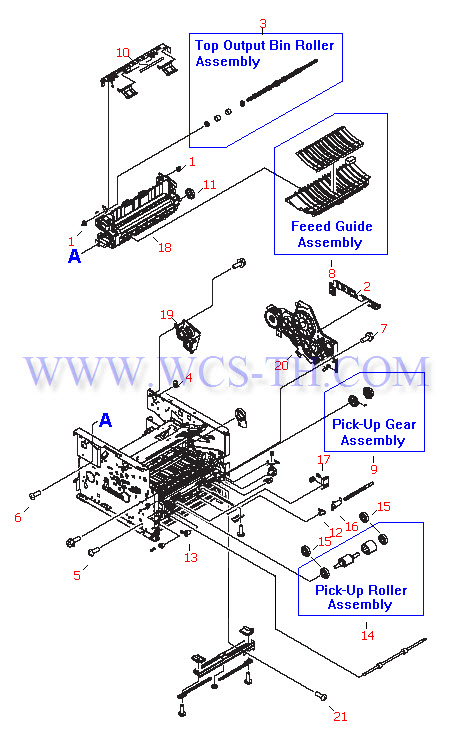
| Pic No. | Parts ID | Parts Name | Link |
| 1 | RC1-3665-000CN | Shaft bushing/retainer - Small plastic cylinder with four nubs that twist - Locks into the side frame - Holds the top output bin roller in the top of the fusing assembly (two used) | Find 1 |
| 2 | RC1-3731-020CN | Cable guide - L-shaped plastic guide with offset fingers - For routing cables through the printer - Mounts on the back of the main drive gear assembly | Find 2 |
| 3 | RL1-0527-000CN | Top output bin delivery roller assembly - Plastic rod with four rubber wheels (two narrow and two wide) - Mounts on top of the fusing assembly | Find 3 |
| 4 | RU5-0332-000CN | 19-tooth gear (White plastic) - Mounts on the end of the top output bin delivery roller | Find 4 |
| 5 | XA9-1495-000CN | Wafer head machine screw - M3, 6mm long, No. 2 Phillips recess - Secures metal to sheet metal - Used internally to secure brackets, plates, the pickup solenoid, and the drive motor to the left and right side plates | Find 5 |
| 6 | XA9-1503-000CN | M3 truss head (Flanged) phillips screw (Black oxide finish) - 6mm long - Typically used to secure plastic parts to the metal side plates and the engine control board to the support pan | Find 6 |
| 7 | XA9-1504-000CN | M3 truss head (flanged) screw - 8mm long - Typically used to secure metal assemblies to the left and right side plates | Find 7 |
| 8 | RM1-1286-000CN | Paper feed guide assembly - Support structure to guide the paper into the fusing assembly - Ribbed plastic frame with metal guide plate - Mounts in front of the fusing assembly (below the toner cartridge) | Find 8 |
| 9 | RM1-1301-000CN | Double gear assembly - Includes the gear body, inset gear (both with a toothless area) and compression spring - For driving the paper pickup roller - Mounts on the right side plate assembly | Find 9 |
| 10 | RM1-2340-000CN | Paper retainer assembly - Bracket assembly with two flapper levers - Keeps paper in the top output bin from sliding back into the printer - Mounts to the top of the fusing assembly | Find 10 |
| 11 | RU5-0331-000CN | 29-tooth gear (White plastic) - Main drive gear for the fusing assembly - Mounts on the right end of the fusing assembly | Find 11 |
| 12 | RB2-2895-000CN | Shaft bushing/retainer - Right side pickup roller support bushing - Mounts on and retains the right end of the pickup roller shaft | Find 12 |
| 13 | RB2-2896-000CN | Shaft bushing/retainer - Left side pickup roller support bushing - Mounts on and retains the left end of the pickup roller shaft | Find 13 |
| 14 | RL1-0540-000CN | Paper pickup roller - Includes the D shaped pickup roller spindle with the rubber tire - Does NOT include the idler rollers on each side of the pickup roller | Find 14 |
| 15 | RC1-3470-000CN | Idler roller (plastic) - Free wheeling roller - Two used - Mounts on each side of the paper pickup roller (two used) | Find 15 |
| 16 | RC1-3472-000CN | Paper sensor flag - Cylindrical plastic piece with a flag on each end (One senses the paper, the other activates the photo-sensor) - Mounts on the paper pickup drive shaft | Find 16 |
| 17 | RU5-2323-000CN | Compression spring - Applies pressure to the idler roller arm (two used) - Mounts in the middle front of the print engine assembly | Find 17 |
| 18 | RM1-1289-080CN | Fusing assembly - Bonds toner to paper with heat - For 110V to 127VAC operation - Mounts to the upper rear of the print engine assembly | Find 18 |
| 18 | RM1-2337-000CN | Fusing assembly - Bonds toner to paper with heat - For 220V to 240VAC operation - | Find 18 |
| 19 | RM1-1305-000CN | Top output gear assembly - Includes three white plastic gears mounted on a support bracket - Drives the top output bin roller - Mounts on the upper rear corner of the right side plate assembly | Find 19 |
| 20 | RM1-1299-020CN | Main drive gear assembly - Large plate with ten drive gears and the single sheet priority drive clutch (SL2) - Mounts on the right side plate assembly | Find 20 |
| 21 | XB4-7401-005CN | M4 pan-head phillips screw with self-tapping threads - 10mm long | Find 21 |
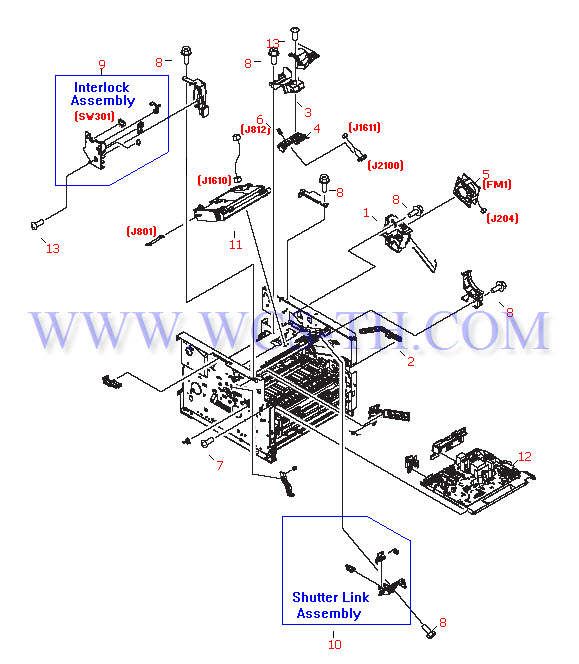
Internal Components (2 of 4)
| Pic No. | Parts ID | Parts Name | Link |
| 1 | RC1-3537-020CN | Fan Holder assembly - Plastic fan bezel with airflow ports - Directs airflow to the various parts of the printer - Mounts on the right side plate assembly | Find 1 |
| 2 | RC1-3544-020CN | Cam arm - Dogleg shaped arm - Disengages the toner cartridge drive gear when the toner cartridge access door is opened - Mounts between the access door and the main drive gear assembly | Find 2 |
| 3 | RC1-3550-000CN | Memory tag arm holder - Supports the tag arm assembly (toner cartridge memory reader) - Mounts towards the right end of the laser/scanner support shelf | Find 3 |
| 4 | RC1-3551-000CN | Tag arm - Spring loaded arm that holds the memory contact and cable (contacts the memory in the toner cartridge) - Mounts in the tag arm holder (Towards the right end of the laser/scanner support shelf) | Find 4 |
| 5 | RK2-0428-000CN | Fan assembly - Includes the small cooling fan and cable - Mounts in the fan housing / air flow guide on the right side plate assembly | Find 5 |
| 6 | RU5-2335-000CN | Compression spring - Applies downward pressure on the memory tag arm to contact the toner cartridge | Find 6 |
| 7 | XA9-1503-000CN | M3 truss head (Flanged) phillips screw (Black oxide finish) - 6mm long - Typically used to secure plastic parts to the metal side plates and the engine control board to the support pan | Find 7 |
| 8 | XA9-1504-000CN | M3 truss head (flanged) screw - 8mm long - Typically used to secure metal assemblies to the left and right side plates | Find 8 |
| 9 | RM1-1467-030CN | Interlock switch assembly - Disables the printer when the left side cover is removed - Mounts in the upper front corner of the left side plate assembly | Find 9 |
| 10 | RM1-1464-000CN | Shutter link assembly - Spring loaded link which engages the shutter on the laser/scanner assembly (blocking the laser beam) when the toner cartridge access door is opened - Mounts on the left front of the laser/scanner support shelf | Find 10 |
| 11 | RM1-1470-050CN | Laser/scanner assembly - Mounts on the laser/scanner support shelf | Find 11 |
| 12 | RM1-1242-030CN | Engine control unit (ECU) PC board - Control and power supply board for the printer (For 110V to 127V operation) - Does NOT includes the power cord connector or power switch - Mounts in the bottom of the printer | Find 12 |
| 12 | RM1-1243-030CN | Engine controlunit (ECU) PC board - Control and power supply board for the printer (For 220V to 240V operation) - Does NOT includes the power cord connector or power switch - Mounts in the bottom of the printer | Find 12 |
| 12 | RM1-1327-030CN | Engine control unit (ECU) PC board assembly - Includes the PC board, bottom pan, standoffs, and gear cover (For 110V to 127V operation) - Does NOT includes the power cord connector or power switch - Mounts in the bottom of the printer | Find 12 |
| 12 | RM1-1463-030CN | Engine control unit (ECU) PC board assembly - Includes the PC board, bottom pan, standoffs, and gear cover (For 220V to 240V operation) - Does NOT includes the power cord connector or power switch - Mounts in the bottom of the printer | Find 12 |
| 13 | XB4-7300-809CN | M3 self-tapping pan head phillips screw (Black oxide finish) - 8mm long - Used to secure the memory tag assembly to the laser/scanner support shelf | Find 13 |
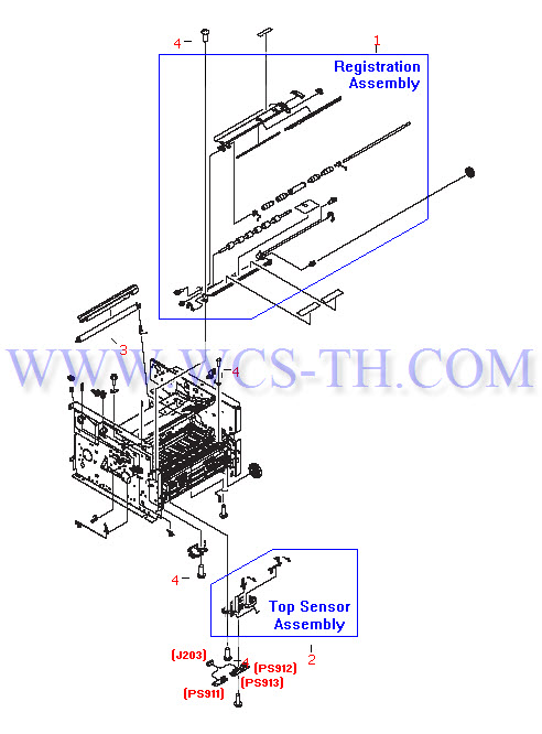
Internal Components (3 of 4)
| Pic No. | Parts ID | Parts Name | Link |
| 1 | RM1-2339-000CN | Registration roller assembly - Includes the frame, the two roller assemblies, and the upper transfer guide - Mounts in the front middle of the print engine assembly | Find 1 |
| 2 | RM1-1283-000CN | Top sensor assembly - Includes the bracket and flags for the top of page detection sensor (PS912), and paper width detection sensor (PS913) - Mounts behind the registration roller assembly | Find 2 |
| 3 | RM1-1471-000CN | Transfer roller assembly - Transfers static charge to the media being printed on - Mounts in front of the paper feed guide assembly | Find 3 |
| 4 | XB4-7401-005CN | M4 pan-head phillips screw with self-tapping threads - 10mm long | Find 4 |
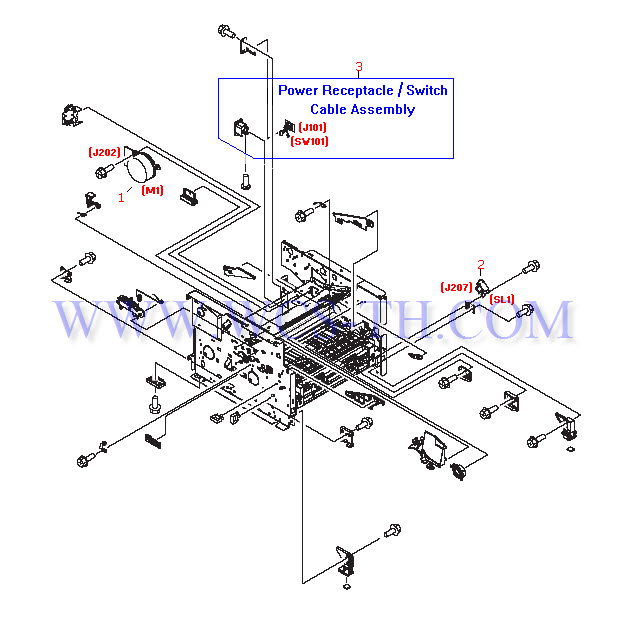
Internal Components (4 of 4)
| Pic No. | Parts ID | Parts Name | Link |
| 1 | RK2-0419-000CN | DC stepper motor assembly - Drives all rollers and fusing assembly via the main drive gear assembly - Mounts on the inside rear of the right side plate assembly | Find 1 |
| 2 | RK2-0424-000CN | 24V DC Solenoid (SL1) - Engages the pickup roller gear/clutch assembly for tray 2 (250-sheet tray) - Mounts on the right side plate assembly | Find 2 |
| 3 | RM1-1249-000CN | Power receptacle and switch cable assembly - Includes the power cord receptacle, power switch, and cable assembly - Mounts in the lower rear corner of the right side plate assembly | Find 3 |
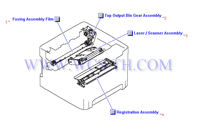
Main Assembly Locator (1 of 2)
| Pic No. | Parts ID | Parts Name | Link |
| 1 | RM1-1289-080CN | Fusing assembly - Bonds toner to paper with heat - For 110V to 127VAC operation - Mounts to the upper rear of the print engine assembly | Find 1 |
| 1 | RM1-2337-000CN | Fusing assembly - Bonds toner to paper with heat - For 220V to 240VAC operation - | Find 1 |
| 2 | RM1-1305-000CN | Top output gear assembly - Includes three white plastic gears mounted on a support bracket - Drives the top output bin roller - Mounts on the upper rear corner of the right side plate assembly | Find 2 |
| 3 | RM1-1470-050CN | Laser/scanner assembly - Mounts on the laser/scanner support shelf | Find 3 |
| 4 | RM1-2339-000CN | Registration roller assembly - Includes the frame, the two roller assemblies, and the upper transfer guide - Mounts in the front middle of the print engine assembly | Find 4 |
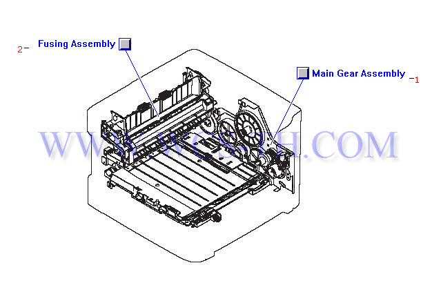
Main Assembly Locator (2 of 2)
| Pic No. | Parts ID | Parts Name | Link |
| 1 | RM1-1299-020CN | Main drive gear assembly - Large plate with ten drive gears and the single sheet priority drive clutch (SL2) - Mounts on the right side plate assembly | Find 1 |
| 2 | RM1-1289-080CN | Fusing assembly - Bonds toner to paper with heat - For 110V to 127VAC operation - Mounts to the upper rear of the print engine assembly | Find 2 |
| 2 | RM1-2337-000CN | Fusing assembly - Bonds toner to paper with heat - For 220V to 240VAC operation - | Find 2 |
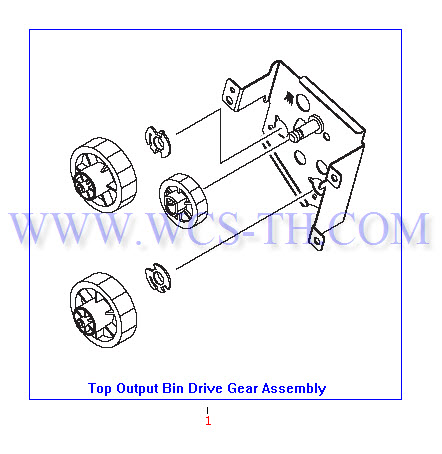
Top Output Bin Drive Gear Assembly
| Pic No. | Parts ID | Parts Name | Link |
| 1 | RM1-1305-000CN | Top output gear assembly - Includes three white plastic gears mounted on a support bracket - Drives the top output bin roller - Mounts on the upper rear corner of the right side plate assembly | Find 1 |