คุณยังไม่มีสินค้าในรถเข็น

Engine Control PC Board and Related Parts
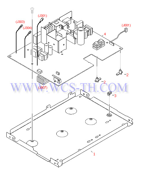
| Pic No. | Parts ID | Parts Name | Link |
| 1 | RA0-1127-000CN | Support pan (case) for the engine controller PC board - Metal pan which also acts as part of the bottom of the printer | Find 1 |
| 2 | RA0-1128-000CN | Printed circuit board spacer - Mounts between the engine control PC board and the metal support pan (six used) | Find 2 |
| 3 | WT2-5694-000CN | Snap-in cable clamp - Secures the drive motor cable from the controller PC board to the metal support pan | Find 3 |
| 4 | RG0-1012-040CN | Engine control PC board - Control and power supply board for the printer (For 110V to 127V operation) - Mounts in the bottom of the printer | Find 4 |
| 4 | RG0-1029-050CN | Engine control PC board - Control and power supply board for the printer (For 220V to 240V operation) | Find 4 |
External Case Parts
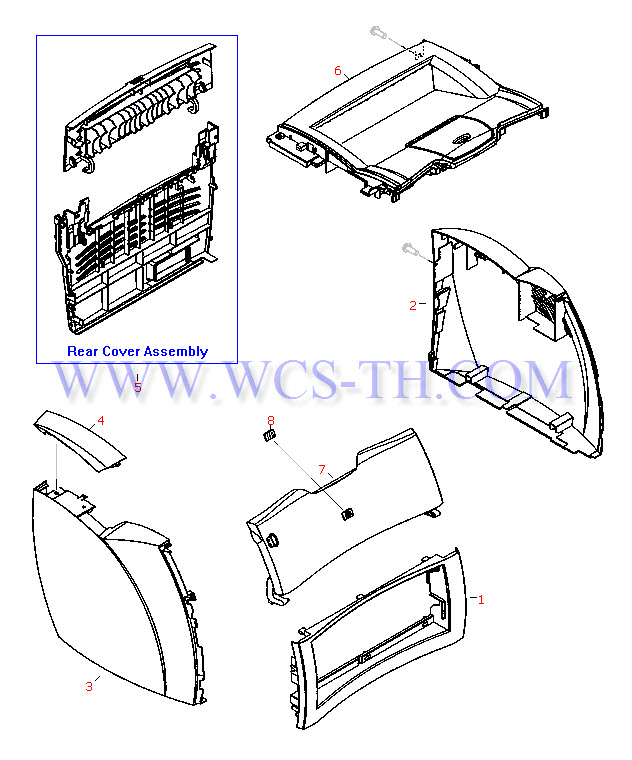
| Pic No. | Parts ID | Parts Name | Link |
| 1 | RA0-1177-000CN | Front cover - Lower front of printer - With opening for inserting the paper input tray assembly | Find 1 |
| 2 | RA0-1178-000CN | Right side cover assembly - Has molded-in air intake louvers | Find 2 |
| 3 | RA0-1179-000CN | Left side printer cover - Covers the USB and parallel port Connectors (On the formatter board) | Find 3 |
| 4 | RA0-1183-000CN | Connector cover - Small rectangular plastic cover - Mounts on top of the left side cover - Covers the connector for the optional copier/scanner if not installed | Find 4 |
| 5 | RG0-1016-000CN | Rear cover assembly - Includes rear cover and fold down face-up (or straight through) paper output tray (Tray is NOT sold separately) | Find 5 |
| 6 | RG0-1017-020CN | Top cover assembly - Has face-down paper output tray molded into it - Mounts to top of printer | Find 6 |
| 7 | RG0-1015-000CN | Toner cartridge door - Fold down door used when accessing the toner cartridge - Mounts to the top of the front cover | Find 7 |
| 8 | 7121-8042 | HP logo (jewel) - for HP LaserJet series printers - Mounts to the toner cartridge door | Find 8 |
Fusing Assembly Parts
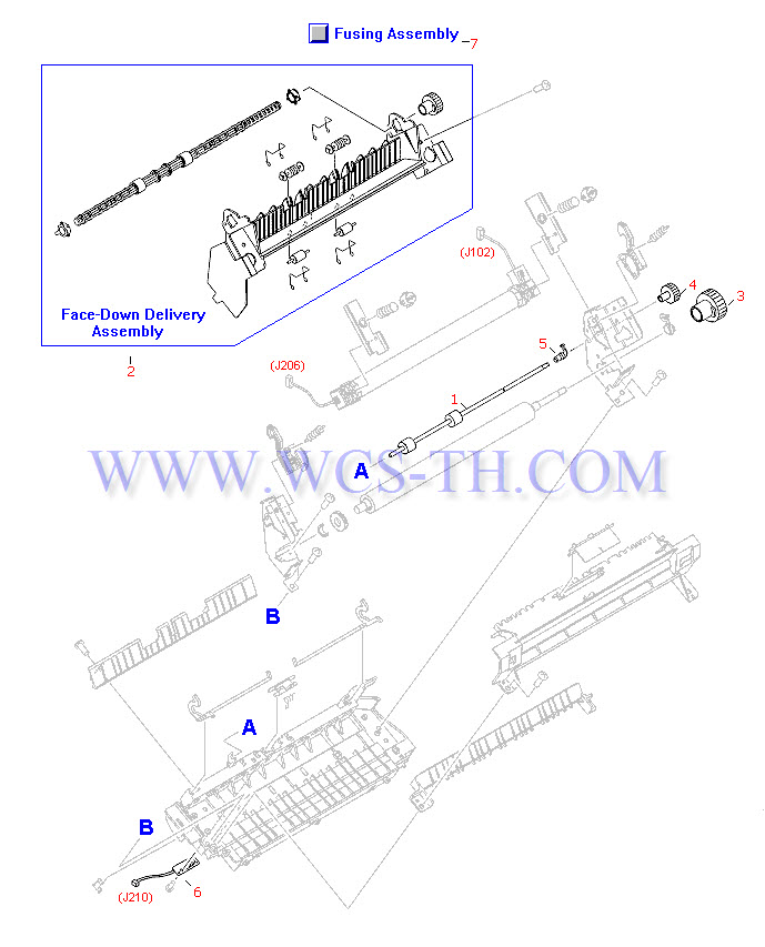
| Pic No. | Parts ID | Parts Name | Link |
| 1 | RF0-1003-000CN | Face-up (straight through) output roller - Metal shaft with two rollers - Mounts on the fusing assembly behind the pressure roller | Find 1 |
| 2 | RG0-1010-000CN | Output roller assembly - Includes face-down delivery roller, four spring-loaded pressure rollers, support frame, and drive gear - Delivers printed pages to the output tray on top of the printer - Mounts on the top rear of the fusing assembly | Find 2 |
| 3 | RA0-1088-000CN | 29 tooth gear - Mounts on the end of the pressure roller - Largest of the three gears on the fusing assembly | Find 3 |
| 4 | RA0-1089-000CN | 17 tooth gear - Mounts on the end of the face-up output roller - Center gear of three gears on the fusing assembly | Find 4 |
| 5 | RA0-1104-000CN | Roller bushing/retainer - Mounts on the right end of the face-up output roller - Also retains the shaft in the fusing assembly | Find 5 |
| 6 | RG0-1082-000CN | Delivery sensor PC board - Small board with optical flag sensor (Flag not included) - For sensing paper output - Mounts on the bottom center of the fusing assembly | Find 6 |
| 7 | RG9-1494-000CN | Fusing assembly - For 220VAC to 240VAC operation - Bonds the toner to the paper with heat - Mounts in the upper rear of the printer | Find 7 |
Internal Components (1 of 2)
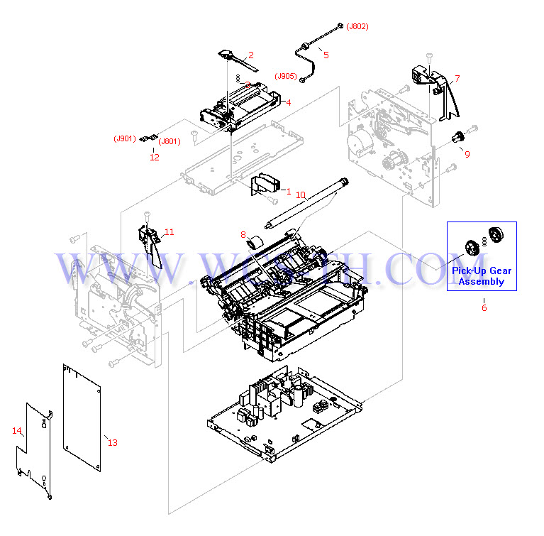
| Pic No. | Parts ID | Parts Name | Link |
| 1 | RA0-1181-000CN | Guide - For the shutter lever on the laser/scanner assembly - Mounts on the metal support bracket for the laser/scanner assembly | Find 1 |
| 2 | RA0-1182-000CN | Shutter lever - Spring loaded lever - Mounts to the top of the laser/scanner assembly | Find 2 |
| 3 | RA0-1169-000CN | Compression spring - Provides tension for the shutter lever - Mounts between the shutter lever and the laser/scanner assembly | Find 3 |
| 4 | C7044-69001 | Laser/scanner assembly - Mounts on top of the print structure frame | Find 4 |
| 5 | RG0-1074-020CN | Cable assembly with ferrite - 4-pin (F) connector on both ends - 35.7cm (14.1in) long - From laser/scanner assembly to formatter board | Find 5 |
| 6 | RG0-1020-000CN | Gear/clutch assembly - Includes two gear bodies and internal spring - Mounts on the right end of the paper pickup shaft | Find 6 |
| 7 | RA0-1184-000CN | Right side cover mounting support - Front cover support - Mounts on the upper right corner of the right side plate | Find 7 |
| 8 | RL1-0303-000CN | Paper pickup roller (D-shaped roller) - Picks up media from the paper input tray - Clips in the holder on the paper pickup shaft | Find 8 |
| 9 | RA0-1172-000CN | 17-tooth gear assembly - Includes the 17-tooth gear mounted on a black plastic lever/bracket - Mounts to the right side plate | Find 9 |
| 10 | RG9-1483-000CN | Transfer roller assembly - Transfers static charge to the media being printed on - Mounts in the top rear of the paper pickup assembly | Find 10 |
| 11 | RG0-1024-080CN | Control panel assembly - Includes the control button and indicator LED's mounted on the left front cover support - Mounts on the upper left corner of the left side plate | Find 11 |
| 12 | RH2-5440-020CN | Flex cable - Has two 10-pin (M) edge connectors - 11.4cm (4.5in) long - From laser/scanner assembly to formatter board | Find 12 |
| 13 | C7857-60001 | Formatter PC board - Includes connectors for the USB and parallel ports, and optional copier/scanner - Mounts on the left side plate | Find 13 |
| 14 | C7044-00001 | RFI shield - Metal plate that covers the formatter board - Mounts on the left side plate | Find 14 |
Internal Components (2 of 2)
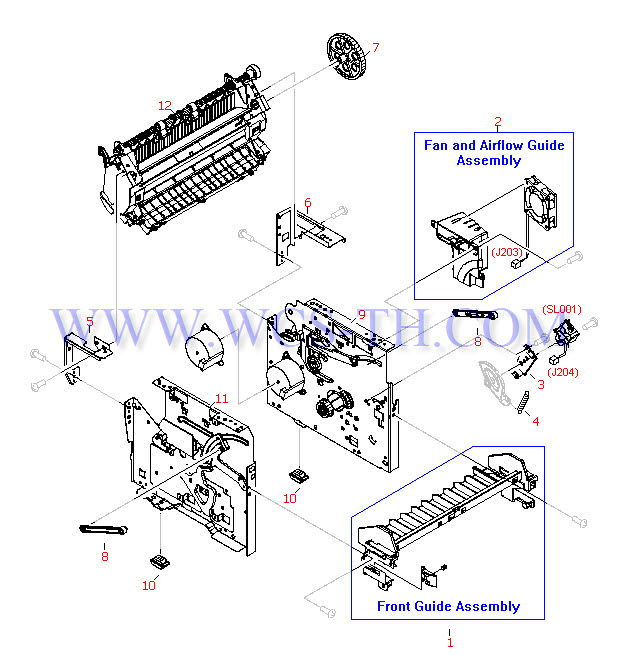
| Pic No. | Parts ID | Parts Name | Link |
| 1 | RG0-1022-000CN | Front guide assembly - Ribbed plastic piece that runs the width of the printer - Mounts to the front of the left and right side plates | Find 1 |
| 2 | RG0-1030-000CN | Fan and airflow guide assembly - Mounts to the upper front on the right side plate | Find 2 |
| 3 | RA0-1173-000CN | Mounting support - Metal piece that supports the paper pickup solenoid (SL001) - Mounts on the right side plate | Find 3 |
| 4 | RA0-1175-000CN | Tension spring - Provides tension for lever - Mounts on the lower front on the right side plate | Find 4 |
| 5 | RA0-1185-000CN | Left side fuser bracket (L-shaped) - Provides mounting support for the fusing assembly - Mounts to the upper rear corner of the left side plate | Find 5 |
| 6 | RA0-1186-000CN | Right side fuser bracket (L-shaped) - Provides mounting support for the fusing assembly - Mounts to the upper rear corner of the right side plate | Find 6 |
| 7 | RA0-1176-000CN | 69 tooth gear - Large gear with ribs and six small holes - Mounts on on a rod in the upper rear corner of the right side plate | Find 7 |
| 8 | RA0-1023-000CN | Connecting link - Connects between the sliding linkage on the left and right side plates and the toner cartridge access door (two used) | Find 8 |
| 9 | RG0-1001-040CN | Right side plate assembly - Includes the right side plate, drive motor, most all drive gears, and cam levers - Does not come with the pickup roller solenoid or 69 tooth gear | Find 9 |
| 10 | RA0-1197-000CN | Rubber foot | Find 10 |
| 11 | RG0-1002-060CN | Left plate assembly - Left side of internal printer mechanism - Plate that the formatter PC board mounts to | Find 11 |
| 12 | RG9-1494-000CN | Fusing assembly - For 220VAC to 240VAC operation - Bonds the toner to the paper with heat - Mounts in the upper rear of the printer | Find 12 |
Main Assembly Locator
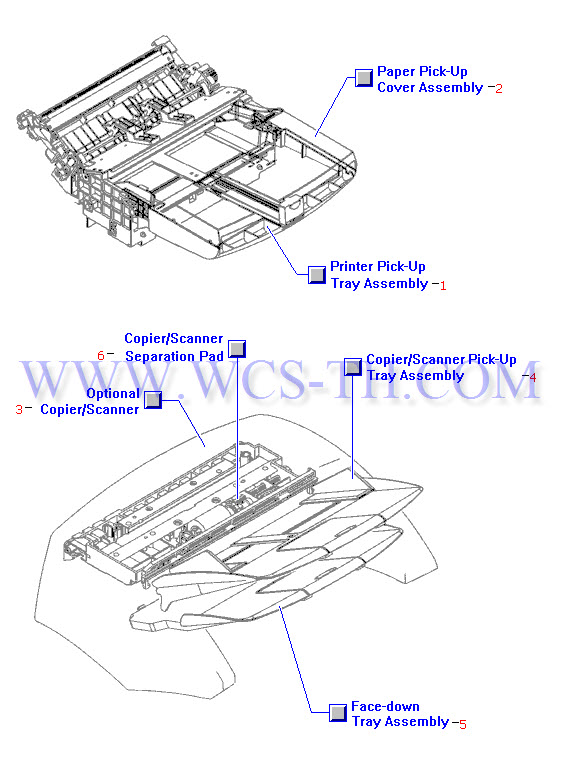
| Pic No. | Parts ID | Parts Name | Link |
| 1 | RG0-1013-000CN | Printer input paper tray assembly - Includes bottom tray, blue paper length adjustment lever, and extension arm (Does NOT include the paper tray cover) | Find 1 |
| 2 | RG0-1014-000CN | Paper tray cover assembly - Includes clear plastic cover with width adjustment guides (Blue) for 'priority' paper input | Find 2 |
| 3 | C7045-69001 | Copier/scanner assembly | Find 3 |
| 4 | RG0-1069-000CN | Pickup tray assembly - Paper input tray for the optional copier/scanner assembly | Find 4 |
| 5 | RG0-1070-000CN | Face-down tray assembly - Paper output tray for the optional copier/scanner assembly | Find 5 |
| 6 | RY7-5055-000CN | Scanner separation pad kit - Kit includes separation pad, separation backing pad and separation pad holder | Find 6 |
Paper Pickup Assembly (1 of 2)
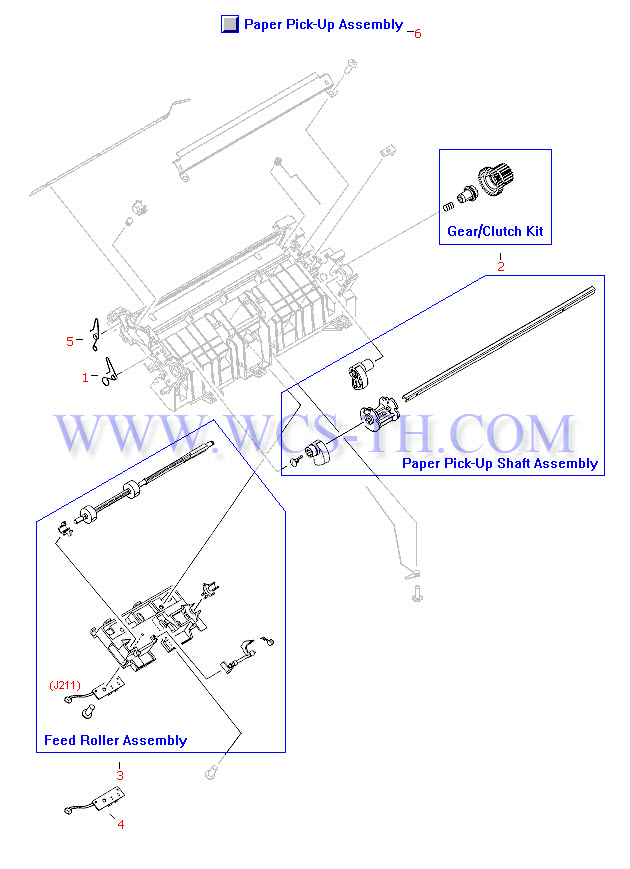
| Pic No. | Parts ID | Parts Name | Link |
| 1 | RA0-1035-000CN | Torsion spring - Provides high voltage connection to the toner cartridge (developing cylinder) - Mounts between the paper pickup roller and the transfer roller on the left side of the paper pickup assembly | Find 1 |
| 2 | RY7-5081-000CN | Gear/clutch assembly kit - Includes double-gear body, shaft attachment piece and spring - For driving the paper feed roller | Find 2 |
| 3 | RG0-1005-000CN | Paper feed roller assembly - Includes feed roller, feed roller base assembly, retainer bushings, paper input leading edge sensor, sensor flag and spring | Find 3 |
| 4 | RG0-1072-000CN | Paper sensor PC board - Small board with optical flag sensor (Flag not included) - For sensing leading edge of paper - Mounts on the paper feed assembly in the paper pickup assembly | Find 4 |
| 5 | RA0-1200-000CN | Torsion spring - Provides high voltage connection to the toner cartridge (primary charging roller) - Mounts behind the transfer roller on the left side of the paper pickup assembly | Find 5 |
| 6 | RG0-1003-030CN | Paper pickup assembly - Includes feed roller assembly, separation pad, plastic housing and other associated parts - Does NOT include the pickup roller | Find 6 |
Paper Pickup Assembly (2 of 2)
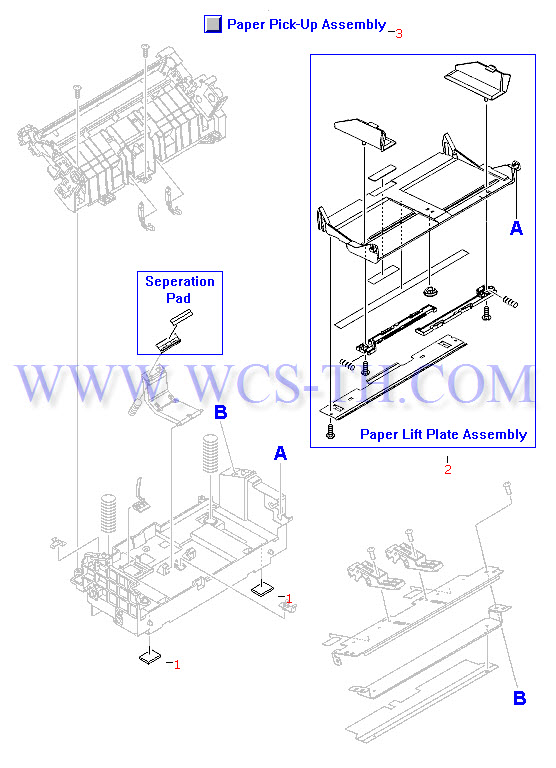
| Pic No. | Parts ID | Parts Name | Link |
| 1 | RA0-1003-000CN | Rubber foot - For bottom of printer - Three used | Find 1 |
| 2 | RG0-1006-000CN | Paper lift plate assembly - Plastic plate assembly that includes the two blue paper width adjusters - Mounts to the top front of the paper pickup assembly | Find 2 |
| 3 | RG0-1003-030CN | Paper pickup assembly - Includes feed roller assembly, separation pad, plastic housing and other associated parts - Does NOT include the pickup roller | Find 3 |